What Is Vinegar Used For and Filling Machine Requirements
What is vinegar used for? Explore food, cleaning, and agricultural uses, plus filling machine requirements for materials, accuracy, and drip…
October 14, 2026

If a filling nozzle keeps dripping or leaves a thin tail after the valve closes, check three things first: pressure at the tip, the product’s viscosity, and the timing between shut-off and nozzle movement. The right shut-off design helps, but a clean result comes from matching the hardware and the process.

Quick answer: Drip usually means liquid is still being pushed through the orifice. Stringing usually means a viscous or elastic product is stretching as the nozzle moves away. Start with a clean seal, then tune a small reverse movement (often called suck-back) and the shut-off timing. Validate every setting with the actual product and container.
Before changing a nozzle, use this guide to matching pumps and nozzles to viscosity so the valve choice fits the material rather than only the machine speed.
When product continues to leave the tip after shut-off, it can land on the container rim, foul tooling, or change the dose. Separate a pressure problem from a material problem: a droplet is usually driven by pressure or a leaking seat, while a long tail is usually caused by viscosity, elasticity, or motion timing.
Unwanted discharge at shut-off stems from a breakdown in fluid cutoff dynamics:
Pressure can remain in the product line after the pump, piston, or screw stops. If the valve closes late or the seat has a small gap, that stored pressure can keep pushing product through the orifice. A positive shut-off close to the outlet and a controlled reverse movement can reduce the pressure at the tip.
Product behavior changes with shear and temperature. Rheology is simply the way a material flows and deforms under those conditions:
| Parameter | Impact on Dispensing Cut-Off | Result if Uncontrolled |
|---|---|---|
| High Tip Temperature | Reduces localized fluid viscosity | Uncontrolled weeping and low-volume drift |
| Excess Residual Pressure | Forces fluid past the valve boundary | Intermittent drooling and neck contamination |
| High Shear Elasticity | Enhances polymer/fluid stretching | Extended filament stringing across tooling |
Table takeaway: A hotter tip, higher residual pressure, or more elastic product each makes a clean break harder. Check the cause that matches the observed defect before changing hardware.
Uncontrolled drip and stringing introduce critical production bottlenecks:
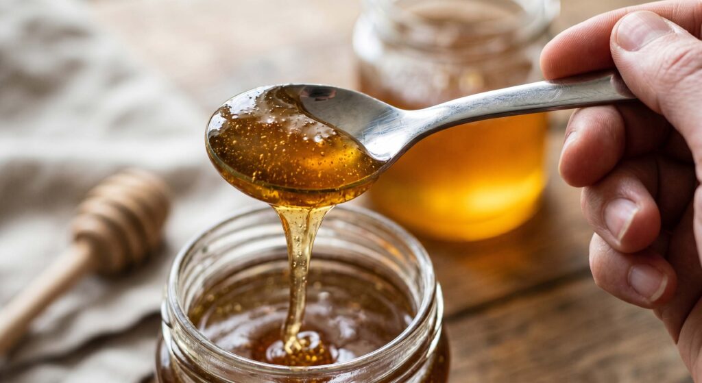
When handling messy shut-off issues on production lines, choosing the right mechanical valve design makes all the difference. On a multi-head line, the valve must also work with the machine motion and controls; see the range of fully automatic filling machines for the wider line context. We build and configure several dedicated positive shut-off architectures to reduce dripping, stringing, and seal contamination right at the discharge point.
| Mechanism Type | Actuation Method | Best Fit | Primary Benefit |
|---|---|---|---|
| Spring-loaded needle | Fluid line pressure | Low to medium viscosity | Self-contained reset |
| Pneumatic or servo plunger | External air or servo drive | Low to high viscosity | Controlled closing force |
| Rotary valve core | Pneumatic or rotary actuator | High-viscosity pastes | Clean shear cut-off |
Table takeaway: Match the valve to product behavior first, then confirm closing force, cleaning access, and seal compatibility during a product trial.
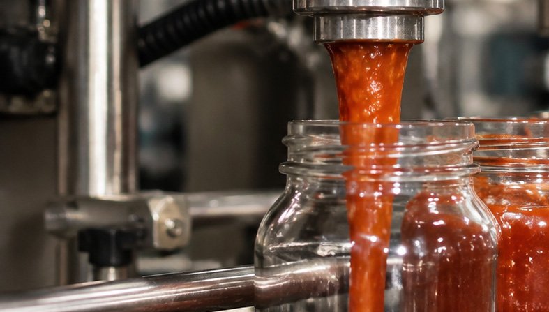
Change one variable at a time and record the result. The sequence below helps separate a sealing problem from a material or motion problem:
Commissioning note: Any stroke, speed, temperature, or pressure value in a machine manual is a starting point for that machine. There is no universal “best” suck-back distance. Validate the final setting with the product, container, nozzle geometry, and line speed.
Controlling drip and stringing at nozzle shut-off comes down to fine-tuning machine parameters. Synchronizing the delivery system with precise drive settings can reduce residual pressure and help prevent tails when validated.
Suck-back decompression relieves residual line pressure at the cut-off point. Pulling the drive back slightly creates negative pressure at the nozzle tip, drawing the trailing meniscus back into the orifice.
Temperature variations directly alter product viscosity. Overheating at the exit orifice thins the fluid and promotes unwanted dripping.
Excessive line pressure during fluid recovery forces material past the valve seat. Balancing recovery parameters helps maintain a stable, repeatable dosing volume.
Mechanical positioning must match fluid cut-off timing to prevent stringing between the nozzle and container.
| Parameter | Too High / Too Fast | Too Low / Too Slow | Validated target |
|---|---|---|---|
| Suck-back distance | Air intake, bubbling, dose inaccuracy | Incomplete break, persistent drool | Smallest validated reverse stroke that breaks the meniscus |
| Suck-back speed | Cavitation, air entrainment | Product stretching, trailing filaments | Fast, controlled response |
| Tip temperature | Fluid thinning, excessive dripping | Freeze-up, nozzle clogging | Validated processing-viscosity window |
| Line back pressure | Post-fill drool, seal weeping | Inconsistent shot repeatability | Minimum pressure for stable dosing |
| Retract timing | Splatter, broken liquid columns | Webbing, exterior nozzle buildup | Snap after positive seal |
Table takeaway: Tune one parameter at a time and keep the setting that produces a clean tip without bubbles, spitting, or dose drift.
Thin liquids need a short, positive path to the outlet. Keep feed pressure stable, avoid unnecessary heat at the tip, and use a seat that closes directly at the orifice. If a screen or mesh insert is used to retain a droplet, check that it does not trap residue or restrict the required flow.
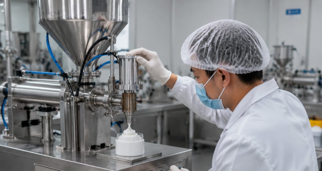
Gels, creams, syrups, and adhesives can stretch into a filament. A sharper mechanical cut, a carefully timed reverse movement, or a rotary shear valve may help. This shoe-cleaning cream filling example about stringing and bubbles shows why the product and the nozzle must be considered together.
Cavitation means bubbles form when the feed side cannot supply the pump smoothly. Entrained air behaves like a spring: it compresses during filling and expands after shut-off, pushing product out of the tip. Check the inlet line, pump speed, product level, and any foaming or degassing step before increasing shut-off force.
For a repeatable viscosity check, the ASTM D2196-20 method for rotational viscosity of non-Newtonian materials is a useful reference. It describes how to measure a material; it does not provide a universal nozzle setting.
For pharmaceutical equipment, FDA 21 CFR 211.65 on equipment construction addresses product-contact surfaces that could adversely affect the product, while 21 CFR 211.67 on equipment cleaning and maintenance requires written, scheduled controls. For food production, 21 CFR 117.40 on equipment and utensils covers cleanable, maintained equipment. These rules support hygiene and maintenance decisions; they do not prove the drip performance of a particular nozzle.
A clean, properly maintained nozzle assembly is essential to stop fluid leakage and product tailing on the line. When mechanical components wear down or suffer from residue buildup, shut-off reliability drops instantly. Regular maintenance prevents unscheduled stops, messy drips, and packaging defects. For a wider fault-isolation checklist, see GDHP’s filling-machine troubleshooting guide.
Mechanical wear at the shut-off interface is a primary cause of nozzle weeping and inconsistent cut-off performance:
Residual product buildup in the fluid path alters flow geometry and hinders shut-off response:
For heated dispensing lines and temperature-dependent fluids, stable thermal management directly controls fluid rheology and cut-off performance:
| Inspection Item | Common Fault | Impact on Nozzle Cut-Off | Corrective Action |
|---|---|---|---|
| Thermocouple Fit | Loose probe or air gap in well | False temperature readings; localized fluid overheating or freezing | Reseat probe firmly against the bottom of the well; tighten locking hardware. |
| Heater Band Contact | Gaps or loose clamping on nozzle body | Uneven heat zones; localized viscosity changes and stringing | Fasten heater bands evenly to ensure uniform surface contact and heat transfer. |
| Zone Calibration | Temperature drift along the discharge path | Inconsistent product cut-off and string formation at the tip | Calibrate PID controllers and verify actual tip temperatures with an external pyrometer. |
Table takeaway: If a wear or temperature fault is found, correct it before changing PLC timing or pressure.
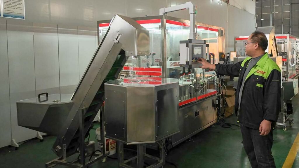
Product characteristics have a direct effect on automatic filling machine cost. Standard liquid applications may use gravity or anti-drip filling systems. Thick creams, pastes, and hot-fill products can require piston filling and insulated or heating-jacketed systems.
For powder and granule filling, the system may need auger fillers, precise metering, anti-clogging design, dust control, and anti-caking measures. Corrosive, toxic, flammable, or high-temperature materials require more specialized construction and safety protection.
Typical upgrades can include:
A fully automatic filling line can extend far beyond the filling station. Depending on the application, the complete system may include:
| Production Stage | Typical Equipment |
|---|---|
| Container preparation | Bottle unscrambler, washer, dryer |
| Filling | Liquid, paste, powder, granule, or capsule filler |
| Closing | Capping machine, sealing machine |
| Identification | Labeling, inkjet coding, laser coding, visual inspection |
| Secondary packaging | Cartoning, shrink wrapping, case packing |
| End of line | Case sealing, palletizing |
A standalone automatic filler has a different cost structure from a turnkey filling and packaging line. Integration adds value by helping equipment work as one process, reducing compatibility issues between separate machines.
Automatic filling equipment may require compliance with ISO 9001, cGMP, and CE standards, along with applicable FDA and hygienic requirements such as EHEDG/3-A. These requirements influence material selection, machine design, documentation, and safety controls.
Factory Acceptance Testing is also part of the project process. We verify the machine online or offline before shipment based on the confirmed production plan. This helps confirm that the equipment is built around the agreed product, container, and operating requirements.
Automatic filling machine pricing is normally project-based rather than fixed. The final cost depends on the agreed configuration, required automation level, production capacity, material handling needs, and the level of line integration.
Our standard project workflow follows clear commercial milestones:
This structure keeps automatic filling machine cost aligned with the actual production needs rather than a generic machine specification.
When running production lines, sudden dripping or tailing at the shut-off point ruins packaging cleanliness and causes seal contamination. Use the symptom to choose the first check rather than changing every setting at once.
While both cause messes around the nozzle orifice, their root causes and appearances differ:
| Issue | Visual Characteristic | Primary Root Cause | Quick Fix |
|---|---|---|---|
| Nozzle Drool / Drip | Liquid droplets or melt puddling at the tip after cut-off. | Residual line pressure, worn seal rings, or lack of suck-back. | Calibrate suck-back distance and replace worn positive shut-off seals. |
| Nozzle Stringing | Fine, spiderweb-like tails stretching between tip and container. | High surface tension, high fluid viscosity, or improper exit speed. | Increase cut-off speed, optimize thermal profile, or use external cut-off tips. |
Table takeaway: A droplet points you toward pressure or sealing; a tail points you toward viscosity, shear, and motion timing.
Set suck-back parameters in the PLC from the actual product viscosity and line speed, then validate the result over repeated cycles:
If you experience fluid or melt weeping past the nozzle seat during high-pressure cycles, check these mechanical factors:
Yes. While dropping the temperature reduces drool by increasing fluid viscosity, excessive cooling causes immediate processing bottlenecks: