CHEMICAL PROCESS · FILLING SERIES

Chemical Filling & Packaging Systems

Build your line around the liquid, the container and the operating environment. Explore filling, capping, sealing and labeling systems for disinfectants, detergents, antifreeze, lubricants and other chemical products, with corrosion resistance and hazardous-area requirements defined for your project.

Chemical production has no room for uncontrolled risk.

Flammability, corrosion, foaming and package variation change how a line should be designed. Define these constraints before selecting the filling machine.

01

Flammable & volatile liquids

Solvent and alcohol formulations may require hazardous-area equipment, static control and ventilation interfaces matched to the site assessment.

02

Corrosive chemistry

Check tanks, pumps, valves, seals, tubing and nozzles against the actual formulation, concentration, temperature and cleaning chemicals.

03

Foam, stringing & drips

Nozzle movement, filling speed, shut-off design and liquid supply conditions must work together to control splashing and keep the sealing area clean.

04

Mixed formats & batches

Small bottles, handled jugs and drums need different support, transfer and closure tooling. Plan recipes and change parts for each pack size.

Product portfolio

Machines for chemical filling & packaging

Explore selected systems for liquid handling, closure control and pack identification. Published specifications below are model-specific; chemical compatibility, hazardous-area suitability and line output must be confirmed for your material and package.

* Published capping speed depends on the container and closure. Labeling accuracy excludes container and label errors. Confirm all performance criteria through agreed sample trials.

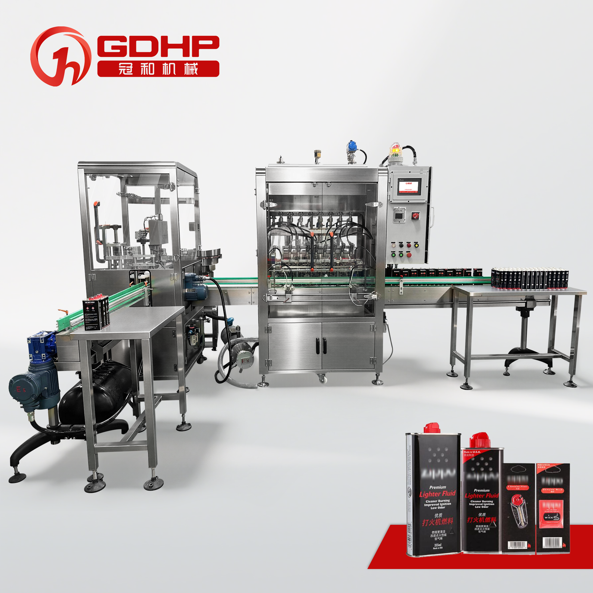
Explosion-Proof Filling System
HAZARDOUS LIQUIDS

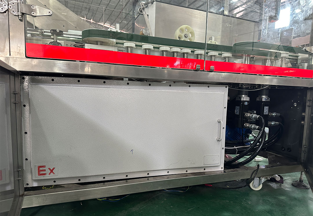
Explosion-Proof Filling System

A filling-and-capping configuration for selected hazardous liquids. Confirm the formulation, container, site classification, grounding, ventilation and required protection scope before final equipment selection.

  • APPLICATIONHazardous liquids
  • PROCESSFilling + capping
  • CONTROLPLC-controlled
  • SAFETYSite assessment required
View machine
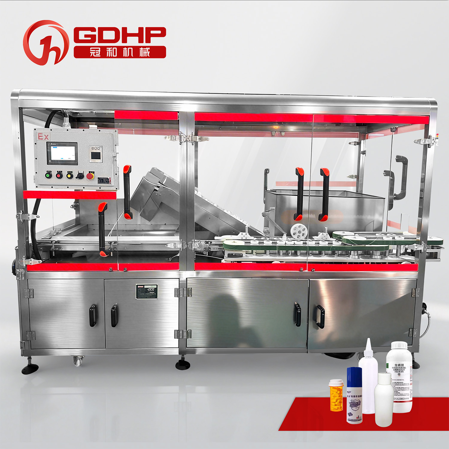
Explosion-Proof Bottle Unscrambler
BOTTLE PREPARATION

Explosion-Proof Bottle Unscrambler

Prepare compatible bottles for an automated chemical line with explosion-proof bottle handling. Confirm the bottle geometry, speed target and hazardous-area interfaces during project engineering.

  • FUNCTIONBottle unscrambling
  • APPLICATIONChemical bottle feeding
  • INTEGRATIONUpstream line
  • SAFETYSite assessment required
View machine
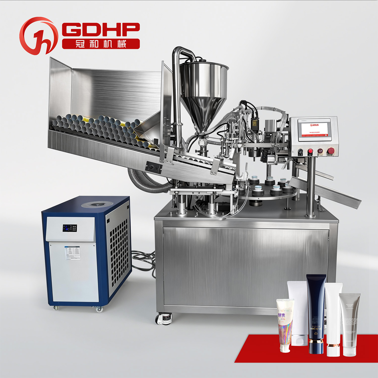
Tube MonoBlock Filling and Sealing Machine
TUBE FILLING & SEALING

Tube MonoBlock Filling and Sealing Machine

An integrated tube filling and sealing machine for compatible creams, adhesives, pigments and other soft-tube products. Confirm tube material, fill range and sealing method with samples.

  • PROCESSTube filling + sealing
  • CONTROLPLC intelligent control
  • TUBE TYPESPlastic / aluminum*
  • APPLICATIONGlue, pigment, creams
View machine
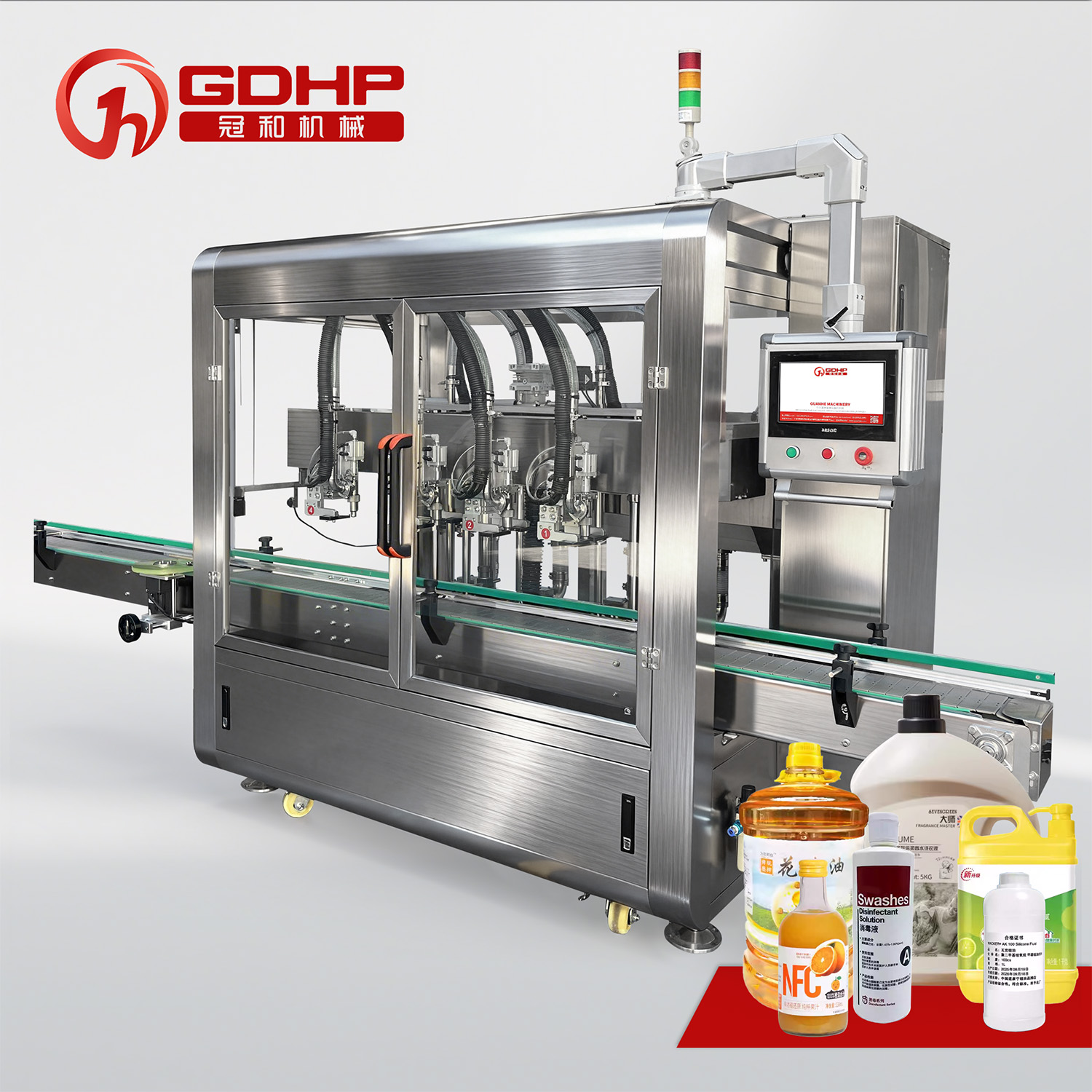
4-Head Tracking Filling Machine
TRACKING FILLING

4-Head Tracking Filling Machine

Filling heads move with the containers for selected detergents, body-wash formulations and antifreeze. The published technical table specifies servo gear metering and PLC touchscreen control.

  • FILL RANGE200–5,000 mL
  • FILLING HEADS4
  • METERINGServo gear
  • CONTROLPLC + touchscreen
View machine
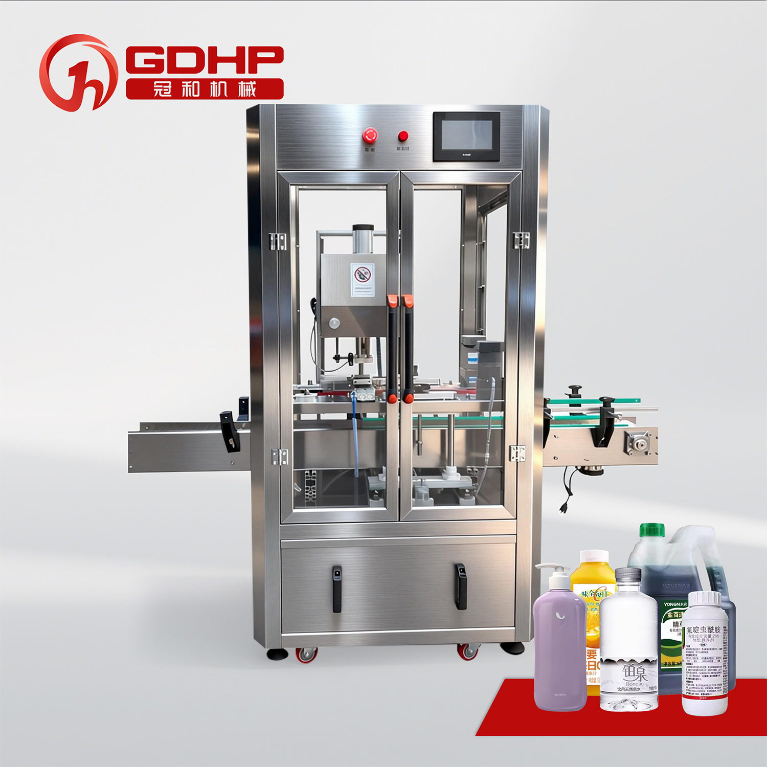
Servo Capping Machine
CLOSURE CONTROL

Servo Capping Machine

Servo-driven torque control for compatible screw caps, pump heads and other closures used with detergents, oils and antifreeze. Match the chuck and bottle support to actual samples.

  • CAP DIAMETER18–65 mm
  • BOTTLE HEIGHT70–330 mm
  • PUBLISHED SPEED50–80 bottles/min*
  • FRAME304 stainless steel
View machine
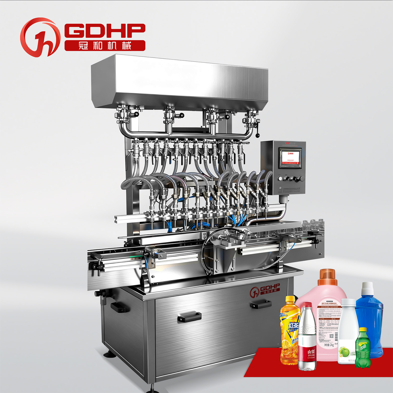
12-Nozzle Linear Gravity Filler
FREE-FLOWING LIQUIDS

12-Nozzle Linear Gravity Filler

Parallel gravity filling for thin, free-flowing liquids such as compatible disinfectants and antifreeze formulations, with PLC control and downstream line integration.

  • MODELGH-A12
  • FILL RANGE100–5,000 mL
  • FILLING HEADS12
  • PUBLISHED OUTPUT2,000–2,800 BPH at 500 mL
View machine

Solution

Match the filling method to the material.

Start with viscosity, density, foaming, particles, corrosiveness and batch size. Then select the metering system, wetted path and nozzle profile together. Enclosed workstations, extraction interfaces and explosion-protection measures can be specified where the product and site assessment require them.
Discuss Your Custom Solution
Peristaltic pump for a replaceable chemical filling path

Weighing & gravity filling

Mechanism: Weighing uses load-cell feedback to reach a target mass; gravity filling controls the flow of free-flowing liquid into the container.

Best fit: Weighing for larger containers and mass-based packs; gravity for thin liquids with stable supply conditions.

Specify: Target mass or volume, density, supply pressure, nozzle count and fast/slow filling stages. Verify performance with representative material.

Peristaltic filling paths

Mechanism: A pump compresses flexible tubing to meter the liquid. Product contact is concentrated in the tubing, connectors and nozzle.

Best fit: Selected low-volume disinfectants and liquids where a replaceable product path helps manage batch changes.

Specify: Chemical-resistant tubing, service life, priming loss and calibration. Tubing compatibility and replacement intervals need application testing.

Servo piston, gear pump or flowmeter

Mechanism: Positive-displacement systems meter a controlled quantity; flowmeters measure the liquid passing through the filling path.

Best fit: Selected detergents, oils, lubricants and other liquids whose viscosity and flow behavior suit the chosen mechanism.

Specify: Viscosity range, particles, shear sensitivity, seal materials and cleaning procedure. Match the nozzle and shut-off profile to foam or stringing behavior.

Selection guide

Choose the line architecture before choosing the model

Choose the architecture from batch size, container stability, fill quantity, closure sequence, safety requirements and downstream operations. Compare the complete line at its intended operating conditions.

PILOT / SMALL BATCH

Compact filling station

Use when batches are short, operators change products frequently and the process needs a manageable starting footprint.

  • Frequent material changes
  • Manual or compact handling
  • Defined cleaning procedure
Integrated production

Integrated filling & capping

Use when bottle transfer, metering, cap placement and capping need coordinated controls and repeatable positioning.

  • Stable bottle transfer
  • Coordinated filling and closure
  • Central PLC/HMI control
End-to-end output

Turnkey filling line

Use when container feeding, filling, sealing, labeling, coding and case packing need coordinated interfaces and balanced output.

  • Line-level output balancing
  • Upstream/downstream integration
  • Safety and acceptance planning

Typical process architecture

From bulk material to a coded chemical pack

Build only the stages your product needs. Connect bulk supply and filling controls with container preparation, closure, identification and secondary packaging; define inspection and rejection points in the line specification.

01Feed & orientBottle unscrambling, jug loading or drum conveying
02Clean or prepareContainer inspection or air cleaning when specified
03Meter & fillMaterial supply, selected metering and controlled shut-off
04Close & sealCap feeding, torque control and compatible foil sealing
05Label & codeProduct identification, batch data and label checks
06Case pack & dispatchPack grouping, case loading and transfer downstream

PROJECT EXPERIENCE

Built around real chemical handling constraints.

Two anonymized project specifications show how the product and package shape the engineering brief. These are specified configurations, not claims of measured production results.

01 · DISINFECTANT

Small bottles, flammable formulation

One project specification covered 30, 60, 80 and 100 mL disinfectant bottles containing isopropyl alcohol. It called for explosion-proof equipment, anti-static circuitry, stainless-steel construction and PLC-controlled filling and capping.

The proposed configuration included a 50 L material tank and peristaltic metering. Multiple bottle sizes required coordinated filling, closure and handling adjustments.

02 · WETTED MATERIALS

A defined material-contact path

Another chemical-line specification called for 316 stainless steel with passivation for product-contact piping, tank connections, the hopper, filling heads and related wetted parts.

The specified workflow connected bottle feeding, filling, capping, labeling, coding and collection. The example illustrates why material requirements should cover the full contact path and the process sequence.

From Requirements to Factory Acceptance

01 Requirements & Sample Testing

Share the safety data sheet, material properties, fill range and output target. Representative containers, closures and an agreed test liquid help evaluate feeding, metering, foaming, shut-off and changeover before the configuration is finalized.

02 Scheme Design & Safety Interfaces

Define the process layout, wetted materials, pump and nozzle selection, closure tooling and control interfaces. Record the site classification, ventilation, grounding, containment and documentation requirements in the agreed project scope.

03 Manufacturing & FAT

Agree on a factory acceptance test plan covering fill quantity, output, closure quality, alarms, rejection and format changes. Use representative packages and a suitable test liquid, record the conditions and results, and resolve deviations against the agreed criteria.

04 Commissioning & Lifecycle Support

Plan installation interfaces, commissioning checks and operator training. Define cleaning, calibration, wear-part replacement and spare-parts needs so the operating team can maintain the filling path, closure tooling and line controls throughout service.

Beginner to project-ready

How to specify a chemical filling line

What does a chemical filling line include?

A chemical filling line transfers a measured amount of liquid or paste into a bottle, jug, pail or drum. Depending on the package, it may integrate container feeding, filling, cap placement, tightening, foil sealing, labeling, coding and secondary packing.

The product name alone does not determine the machine. A water-based cleaner, an alcohol disinfectant and a viscous lubricant can need different materials, metering principles and safety measures even when their containers look similar.

Start with the material and wetted path

Document viscosity, density, foaming tendency, suspended particles, flash point, concentration and operating temperature. Include cleaning agents and any temperature changes during production. Review every wetted component, including seals, hoses, valves and nozzles.

Stainless steel is not universally resistant to chemicals. A 316 or 316L specification can be appropriate for a particular formulation, while another may need a different alloy, compatible polymer or lined path. Confirm compatibility with the actual chemical and service conditions.

Container geometry controls line stability

Bottle base stability, neck position, handles, wall stiffness and closure geometry affect feeding and filling. Small bottles may need nests or pucks, while jugs and drums may need wider guides, roller conveyors or dedicated supports.

Send representative bottles, caps, liners and drawings early. Agree on closure torque, seal checks, change parts and the acceptable container tolerances before committing to automatic sorting and transfer.

Define fill accuracy together with dose and output

Specify whether the acceptance quantity is mass or volume, the target fill, allowable deviation, sampling plan and measurement method. Define output at the intended fill size and formulation, including capping, sealing and downstream constraints.

Published machine speeds are reference points. Factory trials should use the intended container, closure and a representative liquid; record viscosity, temperature, supply conditions and stoppages alongside the measured results.

Plan hazardous-area requirements at line level

For flammable liquids or vapors, provide the safety data sheet and the site hazardous-area classification before equipment selection. Review electrical equipment, ignition sources, static control, ventilation and the location of filling, conveying, capping and sealing stations as one system.

Explosion protection must match the identified hazard and the applicable jurisdiction. A standard filling machine or stainless-steel enclosure is not, by itself, evidence of hazardous-area suitability. Specify the required ratings, certificates and installation interfaces in the project scope.

What to include in your URS

  • Material name, safety data sheet and physical properties
  • Target and minimum/maximum fill volume
  • Container, closure, liner samples and drawings
  • Required output and shift pattern
  • Accuracy definition and test protocol
  • Feeding, cleaning, and closure sequence
  • Product-contact and frame materials
  • Hazardous-area classification and ventilation interfaces
  • Reject, alarm, and traceability logic
  • FAT, site acceptance and documentation scope
  • Available voltage, air, and plant utilities
  • Line layout and future expansion interfaces

Frequently asked questions

Chemical filling machine FAQ

Provide the safety data sheet, flash point, operating temperature, site classification and required local standards. Define the protection requirements for each station and its electrical and control components, together with grounding, ventilation and installation interfaces. The final design requires a site-specific assessment; standard equipment should not be assumed suitable.

Select materials against the formulation, concentration, temperature and cleaning chemicals. Review the complete contact path, including pump internals, seals, tubing and nozzles. 316/316L stainless steel is used in some projects, but it is not a universal solution for acids, alkalis or solvents.

Yes, when the line is designed for an agreed range using adjustable guides, change parts, interchangeable tooling and stored recipes. Actual bottles and closures determine the practical range. Test changeover and restart procedures during acceptance trials.

Assess liquid supply pressure, filling speed, nozzle position and shut-off behavior together. Depending on the formulation, staged filling, bottom-up nozzle movement, anti-drip valves or a suitable suck-back function can help. Verify the settings with the intended liquid and package rather than applying one recipe to every product.

Send the material description and safety data sheet, fill quantities, output target, container and closure drawings, representative samples, available utilities and floor layout. Include cleaning requirements, site classification, labeling/coding needs and the acceptance criteria you want to verify.

Yes, subject to matching container handling, working heights, control interfaces and station capacities. Define accumulation, alarm and rejection logic so a downstream stop does not cause uncontrolled filling. Induction sealing and other potential ignition sources need separate assessment where flammable vapors may be present.

Build Your Custom Solution

Your information is secure - we respect your privacy and will only use these details to contact you.

Build Your Custom Solution