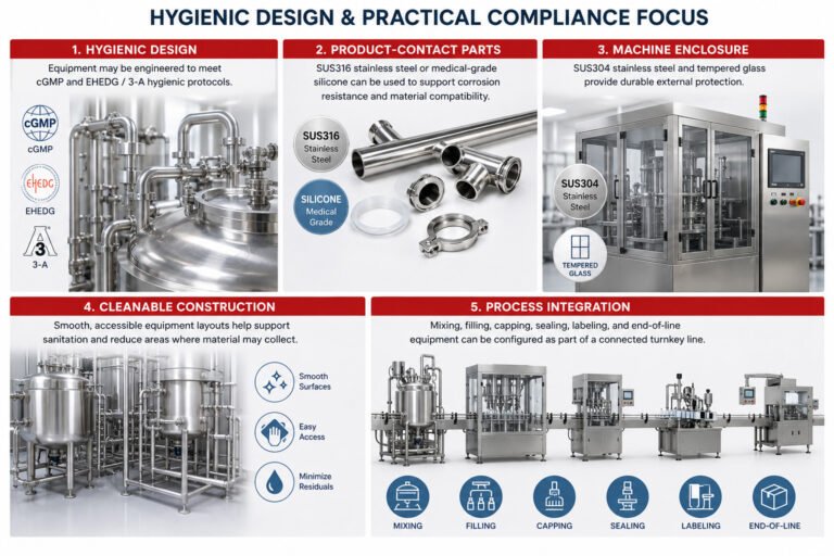
How We Ensure Your Pharmaceutical Machinery Meets GMP Standards
The pharmaceutical machine must comply with GMP, FDA, CE, and ISO9001 regulations, with a design focus on hygiene standards that…
July 25, 2026

Are clogged lines, slow cycle times, or damaged product textures holding back your packaging line? A mismatch between product flow behavior and the pump, valve, or nozzle can undermine an otherwise capable filling system.
Understanding viscosity and particle size limits is critical when learning how to size filling machine pumps, nozzles, and product paths for clean, accurate, and uninterrupted production.
This guide distinguishes published equipment specifications, product-dependent engineering checks, and clearly labelled calculation examples. There is no universal viscosity or particle-size limit: final compatibility must be confirmed for the actual product, temperature, tooling, and required cycle time.

Accurately evaluating product rheology and solid suspension characteristics is the first step in engineering an efficient packaging line. When we design filling systems, matching fluid dynamics to equipment geometry prevents catastrophic line bottlenecks, including pump cavitation, valve plugging, and ruined product textures.
Viscosity measures a fluid’s internal resistance to flow. We evaluate fluid behavior through two distinct metrics:
Formulations can move between bands with temperature and shear rate. Tetra Pak’s rheology chapter cautions that example viscosity values must not be used directly for design calculations.
Liquid behavior changes dramatically once internal shear stress is applied inside pipes and dispensing nozzles:
Particulate-laden products—such as salsas, fruit yogurts, chemical suspensions, and soups—require strict clearance sizing across all fluid paths.
The examples use Dclear = 3 × dmax as an explicitly chosen screening allowance. Alfa Laval Pump Handbook, section 2.1.9, printed p. 25 requires consideration of particle size, concentration, inlet geometry and pump cavity size.
The physical properties of the particulate determine the valve design and internal surface treatment:
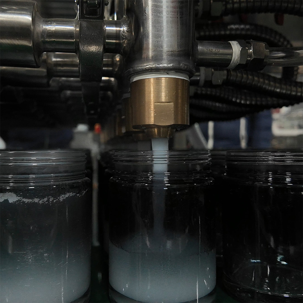
When we size a filling line for heavy creams, thick gels, or chunky suspensions, matching fluid rheology to the correct positive displacement filling pump determines line speed, dosing accuracy, and product integrity. Choosing the wrong pump mechanism results in severe viscous liquid cavitation, crushed particulates, and costly line downtime.
| Pump Technology | Published Reference | Particle / Viscosity Boundary | Selection Check |
|---|---|---|---|
| Piston depositor | UNIFILLER Pro 2000i FS | Up to 1.5-inch cubes (38 mm), per manufacturer. No universal cP limit follows from this specification. | Specified product valve and passages; confirm formulation and attachments. |
| Progressing cavity | NETZSCH NEMO range brochure, p. 3 | 1 mPa·s to 3 million mPa·s across the range (1–3,000,000 cP). | Range-wide capability, not every hygienic dosing model’s envelope. Check feed, geometry, temperature and solids. |
| Rotary lobe | Alfa Laval SRU3/038; table 8.2.1.2a | Maximum spherical solids: 16 mm with bi-lobe rotors; 11 mm with tri-lobe rotors. | Same model designation, different rotors. Not a universal lobe-pump limit. |
| Peristaltic | Watson-Marlow Bredel hose-pump range | High-viscosity and solids-bearing service is described; a universal 10,000 cP ceiling or soft-particles-only rule is not justified. | Industrial hose transfer pumps and small-bore hygienic dosing heads have different limits. |
| Precision gear pump | Selected model’s data sheet and wear limits | No pump-class viscosity or particle-size rating is assigned here. | Check compatibility, abrasiveness, gear clearance and hard solids. |
References: UNIFILLER Pro 2000i FS; NETZSCH NEMO brochure, p. 3; Alfa Laval handbook, printed p. 235; Bredel hose pumps. These are manufacturer-published examples, not independent tests, simultaneous operating maxima, GDHP ratings, or endorsements of GDHP equipment.
Servo-driven and pneumatic piston fillers remain our top recommendation for high-viscosity pastes, batters, and suspended solids.
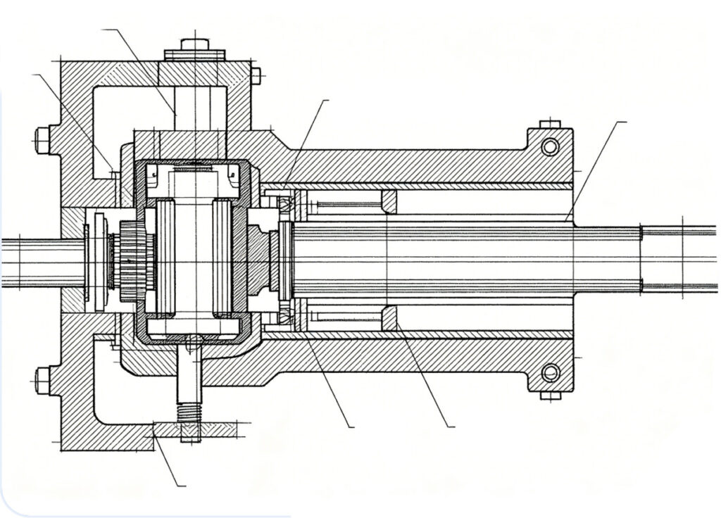
For sterile pharmaceuticals and sensitive emulsions, peristaltic dosing limits product contact to the tubing path. Sterility, cleanability and product integrity still depend on the complete validated process and selected tubing.
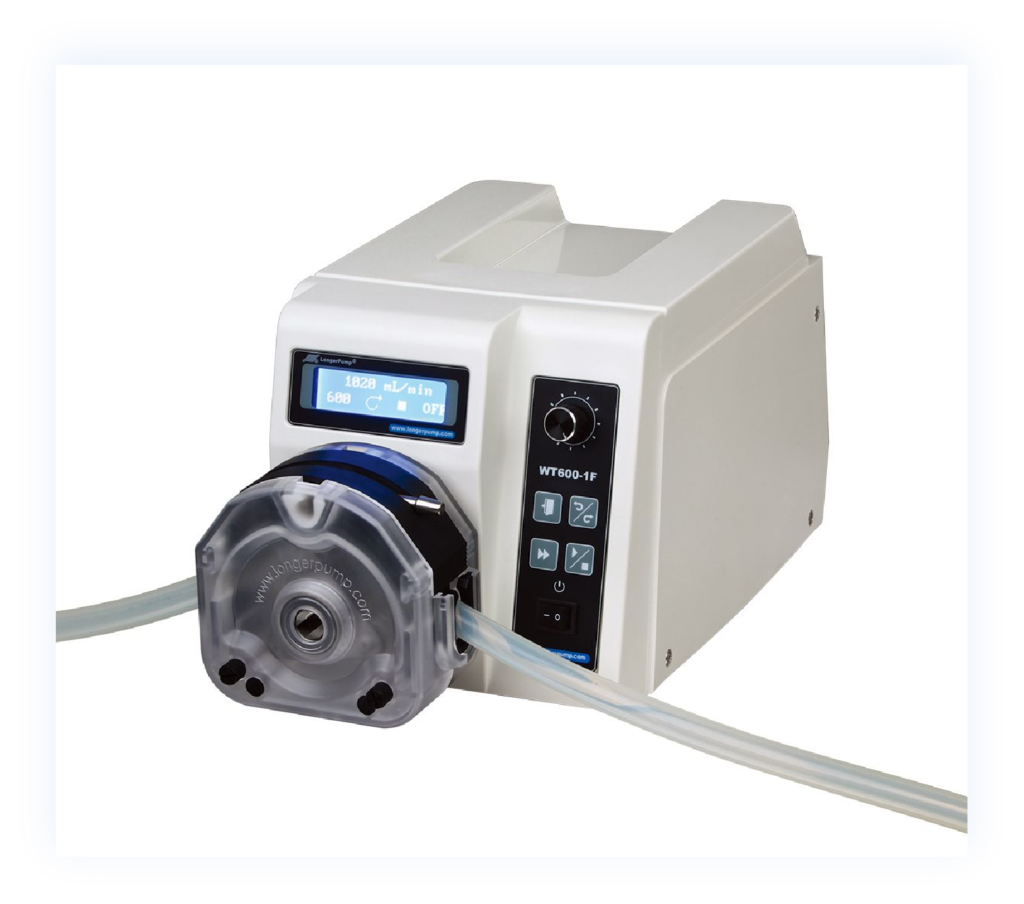
For continuous feed, select geometry and speed for the actual product. Low pulsation does not mean zero pulsation or guaranteed dosing accuracy.
To size your pump drive correctly and prevent motor stalling or fluid cavitation, we use three core engineering metrics:
Size the pump displacement so it operates within its nominal speed window rather than redlining its mechanical stroke:
Viscous fluids generate significant vacuum drops inside suction piping. To eliminate pump cavitation:
Size the drive for pressure duty, viscous drag, seal friction, acceleration and cold starts. Steady-state power alone does not establish peak torque.
Selecting the right liquid filling nozzle sizing is the final and most critical step in safeguarding fill accuracy, container cleanliness, and target line speeds. An improperly sized nozzle leads to product stringing across container rims, excessive foaming, particulate clogs, and costly product giveaway. We balance clear-bore geometry with active mechanical cutoffs to keep your line running cleanly.
Sizing the internal diameter (ID) of a filling nozzle requires balancing fluid velocity against particle geometry:
Different fluid profiles require distinct shut-off mechanisms at the nozzle discharge tip:
Bottom-up diving nozzle systems synchronize nozzle vertical movement with fluid delivery:
High-viscosity and viscoelastic fluids (honey, resin, polymer gels, caramel) tend to form long, sticky liquid tails when the fill stroke ends:

Designing the fluid delivery path is just as critical as selecting the pump itself. When moving viscous liquids or particulate slurries, poor piping layout creates massive line friction, causing pump cavitation, seal failures, and severe fill weight variations. As a professional manufacturer of filling machines, we engineer product delivery manifolds to minimize hydraulic resistance and protect product integrity from the hopper to the nozzle tip.
For a Newtonian liquid in fully developed laminar flow in a straight circular pipe, ΔP = 128μLQ/(πD4). At fixed Q, pressure drop is inversely proportional to D4, a power-law relationship, not an exponential one. At fixed average velocity, ΔP is proportional to 1/D². Poiseuille’s law provides the straight-pipe relationship; non-Newtonian products require an appropriate rheological model.
Under-sizing suction lines is the primary cause of viscous liquid cavitation and pump starving. To maintain stable positive displacement filling:
| Illustrative Actual Pipe ID | Calculated Product Velocity | Calculated Straight-Pipe ΔP |
|---|---|---|
| 25 mm | 0.566 m/s | 5.79 bar |
| 38 mm | 0.245 m/s | 1.09 bar |
| 51 mm | 0.136 m/s | 0.335 bar |
Calculation example, not measured equipment data: Q = 500 mL / 1.8 s = 16.7 L/min; L = 2 m; Newtonian μ = 10 Pa·s (10,000 cP); ρ = 1,000 kg/m³. Reynolds numbers are approximately 1.41, 0.93 and 0.69. Values exclude valves, bends, entry/exit losses and lift. These bores are not standard sanitary tube IDs or recommendations based only on viscosity. Real particulate products also require a suspension/settling check.
Sharp turns and sudden geometry changes create shear hotspots, crush particulate inclusions, and create trapped air pockets:
Every fitting and valve must provide an unobstructed, smooth internal bore:
Many industrial and food products—such as hot-fill jams, wax, chocolate, and petroleum gels—display high viscosity at ambient temperatures but flow easily when heated:
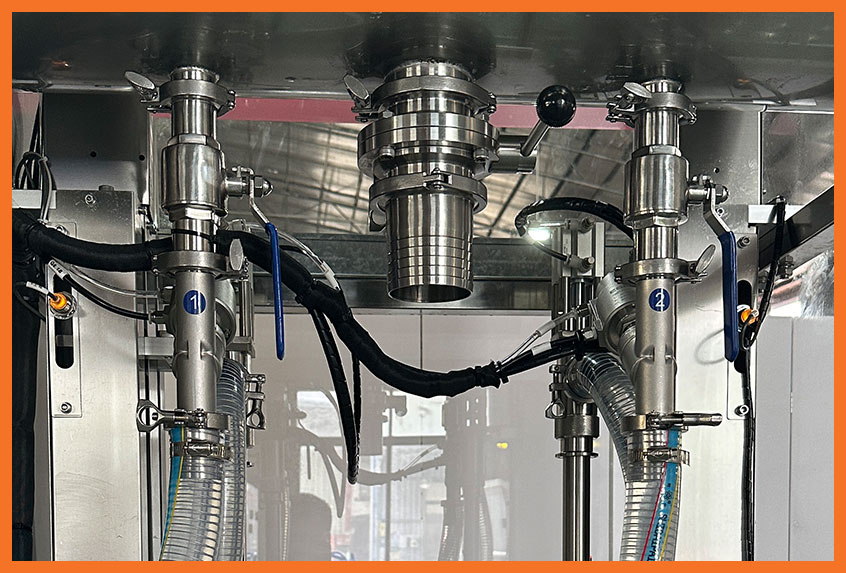
Sizing a pump, product path and nozzle requires a defined duty and product measurements. These four steps distinguish preliminary calculations from the OEM checks and sample tests needed before final dimensions and drive limits are approved.
Before crunching mechanical numbers, we profile the exact physical behavior of the product under target factory floor temperatures:
Define the actual timing sequence. In an indexed, non-overlapping example, effective fill time is total cycle time minus handling overhead. Continuous or overlapping machines need their own timing model, and cylinder refill must also fit the sequence.
For a Newtonian, incompressible liquid in steady, fully developed laminar flow through a straight circular pipe, use the Hagen–Poiseuille relationship. Re = ρvD/μ < 2,000 is a laminar-flow screening check for the Newtonian example, not a substitute for a non-Newtonian model. For shear-dependent foods, see Tetra Pak’s rheology and pressure-drop discussion.
ΔP = 128μLQ/(πD4)
Use μ in Pa·s, L and D in m, and Q in m³/s to obtain ΔP in Pa. Conversions: 1 cP = 0.001 Pa·s; 1 L/min = 1/60,000 m³/s; 1 bar = 100,000 Pa.
To avoid high line resistance: Calculate friction loss for each straight tubing run, elbow, manifold junction, and valve port. Convert fitting friction into equivalent pipe lengths. Add the static vertical lift head (elevation rise from supply reservoir to nozzle tip). Add backpressure generated across the nozzle exit orifice.
Keep head and pressure consistent: Convert pressure using H = ΔP/(ρg), g ≈ 9.81 m/s², before adding lift in metres. Include actual valve, bend, nozzle and inlet losses and transient operation. The Section 4 table gives straight-pipe results only, not a pressure rating or final selection.
With target flow rate and pressure loss (Delta P) established, size the final hardware:
Cycle-time sensitivity example, not a viscosity test: Increasing the illustrative 1.8 s effective fill time by 30–60% gives 2.34–2.88 s. With unchanged 1.2 s overhead, the total cycle becomes 3.54–4.08 s, up 18–36%. The theoretical single-head rate changes from 20.0 to 16.9–14.7 cycles/min. This shows why fill-time and total-cycle changes differ; it does not predict the behavior of a 50,000 cP paste.
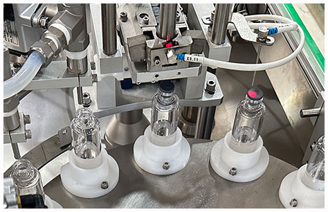
Running viscous pastes and chunk-filled suspensions at high speeds exposes every weak point in your fluid path. When lines choke, nozzles drip, or particulates get crushed, production stalls. As a filling machine manufacturer, we troubleshoot these issues daily on factory floors. Here is how we isolate and resolve the most common flow bottlenecks.
Inadequate inlet replenishment can cause short fills. Cavitation specifically involves local pressure falling below vapor pressure; air entrainment or incomplete refill can produce similar symptoms without being the same mechanism. Check the inlet balance, temperature and timing before choosing a remedy.
Drips and stringing contaminate container seals, create burning on induction sealers, and waste costly product. Inconsistent shut-off mechanisms are almost always the root cause.
Pumping fruit chunks, salsa, or industrial suspensions requires delicate handling to maintain inclusion integrity and ensure equal solid-to-liquid ratios across all filling heads.
Sticky formulations, starches, and heavy fats resist standard clean-in-place cycles, creating contamination hazards and valve sticking.
There is no universal maximum for a standard piston nozzle. The article’s 3:1 clearance ratio is an assumed screening example, not a guarantee. A particle with a 10 mm maximum measured dimension gives a 30 mm initial bore candidate; valves and other restrictions still need checking. Do not automatically reduce the ratio for soft inclusions. UNIFILLER lists up to 38 mm cubes for the Pro 2000i FS with specified passages, subject to product confirmation. Cube side length, spherical diameter and an irregular particle’s longest dimension are different conventions.
Some piston or progressing-cavity platforms cover both after suitable tooling and setting changes, but compatibility is not automatic. Check model-specific viscosity, inlet-feed, seal, valve and temperature limits. Thin liquids may need different shut-off and diving settings; pastes may need larger clear passages and slower intake. Test both products with the actual container, dose and required output.
Shear can change structure, viscosity or aeration, depending on formulation, shear rate and exposure time. Tetra Pak’s rheology guidance distinguishes shear thinning from time-dependent behavior; temporary thinning is not automatically permanent damage. Compare incoming and filled product using agreed texture, inclusion-integrity and stability checks, rather than assuming every gear pump damages emulsions or every low-shear pump preserves them.
There is no universal acceptable pressure drop of 20–30 psi (approximately 1.4–2.1 bar). The pressure budget depends on the pump, tubing, seals, valves, nozzle and temperature, with adequate inlet conditions and pressure protection. Section 4’s Newtonian calculation gives 5.79 bar for 2 m of 25 mm actual-ID pipe, 1.09 bar at 38 mm, and 0.335 bar at 51 mm, excluding fittings and lift. Calculate the complete duty and check each component’s rating; one pressure band is not safe for all lines.