Viscosity and Particle Size Limits: How to Size Filling Machine Pumps, Nozzles, and Product Paths

Are clogged lines, slow cycle times, or damaged product textures holding back your packaging line? A mismatch between product flow behavior and the pump, valve, or nozzle can undermine an otherwise capable filling system.

Understanding viscosity and particle size limits is critical when learning how to size filling machine pumps, nozzles, and product paths for clean, accurate, and uninterrupted production.

This guide distinguishes published equipment specifications, product-dependent engineering checks, and clearly labelled calculation examples. There is no universal viscosity or particle-size limit: final compatibility must be confirmed for the actual product, temperature, tooling, and required cycle time.

John senior engineer and founder

1. Understanding Fluid Rheology and Particle Limits in Liquid Filling

Accurately evaluating product rheology and solid suspension characteristics is the first step in engineering an efficient packaging line. When we design filling systems, matching fluid dynamics to equipment geometry prevents catastrophic line bottlenecks, including pump cavitation, valve plugging, and ruined product textures.

Dynamic vs. Kinematic Viscosity Across Product Classes

Viscosity measures a fluid’s internal resistance to flow. We evaluate fluid behavior through two distinct metrics:

  • Dynamic Viscosity (cP or mPa·s): Measures shear stress relative to shear rate. This is the primary value used to size positive displacement pumps and determine nozzle backpressure.
  • Kinematic Viscosity (cSt): Kinematic viscosity equals dynamic viscosity divided by density: ν (cSt) = μ (cP) / ρ (g/cm³). Use values at the same temperature. The shortcut cP/SG is only approximate when reference-water density is treated as 1 g/cm³. For non-Newtonian products, report apparent viscosity with shear rate and test method.

Formulations can move between bands with temperature and shear rate. Tetra Pak’s rheology chapter cautions that example viscosity values must not be used directly for design calculations.

  • Low viscosity: 1 to <100 cP. Water-like products may suit gravity or pressure-assisted filling; foaming, dose size and nozzle geometry still matter.
  • Medium viscosity: 100 to <5,000 cP. Oils, syrups and formulated liquids may fall here at a specified temperature. Positive-displacement or pressure-assisted feeding can be considered, but viscosity alone does not make either mandatory.
  • High viscosity: 5,000 cP and above, including products above 100,000 cP. Evaluate yield stress and inlet replenishment as well as apparent viscosity. Some pastes need hopper or follower-assisted feeding; the band is not a particular filler’s capacity rating.

Newtonian vs. Non-Newtonian Flow Behaviors

Liquid behavior changes dramatically once internal shear stress is applied inside pipes and dispensing nozzles:

  • Newtonian Fluids: At fixed temperature, viscosity is independent of shear rate. Flow rate is proportional to pressure drop for fully developed laminar flow in a fixed circular pipe; this does not describe every pump or turbulent-flow condition.
  • Shear-Thinning (Pseudoplastic): Apparent viscosity drops as shear rate increases (e.g., ketchup, shampoo, emulsions). High flow velocity through the nozzle lowers fluid resistance, making dispensing easier during high-speed strokes.
  • Thixotropic Fluids: Viscosity decreases over time under continuous agitation or circulation (e.g., industrial gels, heavy pastes). These fluids often require pre-shear circulation loops before entering the metering cylinder.
  • Dilatant (Shear-Thickening): Viscosity spikes when shear is applied (e.g., high-solid slurries, starch suspensions). Pumping these too fast causes sudden line lock-up and severe motor overload.

Particle Clearance: Using a 3:1 Assumption for Initial Screening

Particulate-laden products—such as salsas, fruit yogurts, chemical suspensions, and soups—require strict clearance sizing across all fluid paths.

The examples use Dclear = 3 × dmax as an explicitly chosen screening allowance. Alfa Laval Pump Handbook, section 2.1.9, printed p. 25 requires consideration of particle size, concentration, inlet geometry and pump cavity size.

  • Check the smallest clear opening: Measure the narrowest usable passage through the inlet, valve in its operating position, manifold and nozzle. Measure irregular particles along their maximum dimension and state the method. A 6 mm maximum dimension gives an 18 mm screening bore under the chosen 3:1 assumption; OEM limits and sample trials can require a larger passage or different valve.
  • Suspension Stability: Check solids concentration, density difference, settling or flotation, and mixing throughout the run. Higher carrier viscosity can slow separation but does not guarantee equal particle-to-liquid ratios across heads. Softness alone is not permission to use a smaller clearance ratio.

Hard vs. Soft Particles: Inclusions and Machine Wear

The physical properties of the particulate determine the valve design and internal surface treatment:
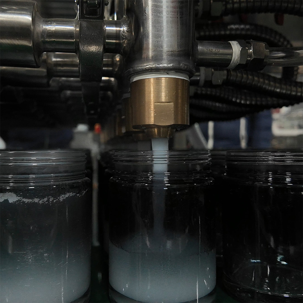
  • Soft, Compressible Inclusions: Fruit pulp, cooked vegetables, and cosmetic soft beads are vulnerable to shear damage. Narrow orifices and high-velocity restrictions will macerate soft inclusions, ruining product texture. These products require wide-bore rotary valves and low-shear piston paths.
  • Hard, Abrasive Inclusions: Seeds, crystalline chemical solids, and mineral slurries cause severe mechanical wear. They scratch cylinder walls, score valve seats, and compromise shut-off seals. Handling hard solids requires hardened stainless steel contact paths, elastomeric valve seats, and generous internal clearances to prevent jamming.
hot filling of blam

2. Selecting and Sizing Filling Machine Pumps for Viscous Products

When we size a filling line for heavy creams, thick gels, or chunky suspensions, matching fluid rheology to the correct positive displacement filling pump determines line speed, dosing accuracy, and product integrity. Choosing the wrong pump mechanism results in severe viscous liquid cavitation, crushed particulates, and costly line downtime.

Pump TechnologyPublished ReferenceParticle / Viscosity BoundarySelection Check
Piston depositorUNIFILLER Pro 2000i FSUp to 1.5-inch cubes (38 mm), per manufacturer. No universal cP limit follows from this specification.Specified product valve and passages; confirm formulation and attachments.
Progressing cavityNETZSCH NEMO range brochure, p. 31 mPa·s to 3 million mPa·s across the range (1–3,000,000 cP).Range-wide capability, not every hygienic dosing model’s envelope. Check feed, geometry, temperature and solids.
Rotary lobeAlfa Laval SRU3/038; table 8.2.1.2aMaximum spherical solids: 16 mm with bi-lobe rotors; 11 mm with tri-lobe rotors.Same model designation, different rotors. Not a universal lobe-pump limit.
PeristalticWatson-Marlow Bredel hose-pump rangeHigh-viscosity and solids-bearing service is described; a universal 10,000 cP ceiling or soft-particles-only rule is not justified.Industrial hose transfer pumps and small-bore hygienic dosing heads have different limits.
Precision gear pumpSelected model’s data sheet and wear limitsNo pump-class viscosity or particle-size rating is assigned here.Check compatibility, abrasiveness, gear clearance and hard solids.

References: UNIFILLER Pro 2000i FS; NETZSCH NEMO brochure, p. 3; Alfa Laval handbook, printed p. 235; Bredel hose pumps. These are manufacturer-published examples, not independent tests, simultaneous operating maxima, GDHP ratings, or endorsements of GDHP equipment.

Piston Pumps: The Benchmark for Pastes, Creams, and Chunky Particulates

Servo-driven and pneumatic piston fillers remain our top recommendation for high-viscosity pastes, batters, and suspended solids.
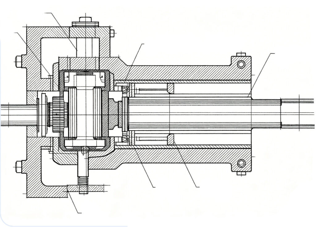
  • Pressure and inlet replenishment: A piston can develop discharge pressure while still failing to refill properly. A product described as 50,000 cP must be checked at its filling temperature, shear rate and intake speed; viscosity alone does not prove that starvation will be avoided.
  • Preserving Inclusions: Large ports and an appropriate product valve can reduce damage, but the full passage needs checking. UNIFILLER lists up to 38 mm cubes for the Pro 2000i FS with its specified valve and passages, and notes that similar products may require further testing.
  • Piston Diameter Matching: Calculate swept volume and usable stroke, then check the manufacturer’s operating window. An illustrative 100 mm cylinder bore needs about 63.7 mm stroke to displace 500 mL geometrically, before leakage, compressibility and calibration corrections. This does not establish a universal 60–80% stroke rule or prevent seal blow-by.
Piston Pump

Peristaltic Pumps: Shear-Sensitive, Sterile, and Abrasive Fluids

For sterile pharmaceuticals and sensitive emulsions, peristaltic dosing limits product contact to the tubing path. Sterility, cleanability and product integrity still depend on the complete validated process and selected tubing.
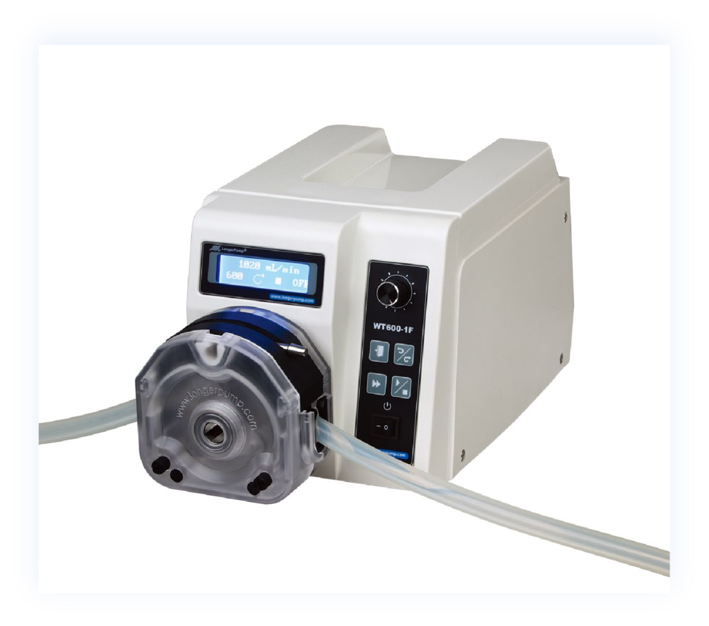
  • Isolated product path: The liquid contacts tubing rather than a pump seal or rotor. This can simplify changeover, but does not by itself establish zero cross-contamination or a sterile system.
  • Gentle Fluid Dynamics: The low-shear roller motion preserves delicate cell structures, polymers, and shear-thinning matrices.
  • Operating Limits: Bredel’s documentation includes high-viscosity and solids-bearing hose-pump service, so 10,000 cP is not a technology-wide ceiling. Do not transfer industrial hose-pump capabilities to a small pharmaceutical dosing tube: check inlet conditions, tube recovery, speed, particle shape, abrasion and dose repeatability for that head.
Peristaltic Pump

Rotary Lobe and Progressive Cavity Pumps: Continuous Flow for Viscous Slurries

For continuous feed, select geometry and speed for the actual product. Low pulsation does not mean zero pulsation or guaranteed dosing accuracy.

  • Progressing Cavity Systems: NETZSCH’s NEMO brochure, p. 3 lists 1 mPa·s to 3 million mPa·s across the range. This supports broad viscosity coverage, not a blanket 1,000,000 cP rating or 25 mm particle allowance for an unspecified filler. Confirm the chosen model’s feed arrangement, stator, speed and pressure duty.
  • Rotary Lobe Units: Alfa Laval table 8.2.1.2a, printed p. 235 lists spherical solids of 16 mm for SRU3/038 bi-lobe rotors versus 11 mm for tri-lobe rotors. Use actual rotor geometry and sample trials instead of treating 15–20 mm as a limit for all rotary-lobe pumps.

Diaphragm and Gear Pumps: Operational Boundaries and Restrictions

  • Gear Pumps: Often suitable for compatible clean oils, resins and syrups. Close gear clearances make abrasive or hard solids a wear and jamming concern; obtain a model-specific limit instead of publishing a universal 0 mm tolerance or assuming every trace of grit causes immediate lockup.
  • Air-Operated Diaphragm (AODD): Well-suited for fluid transfer and shear-sensitive products, but stroke pulsations require active pulsation dampeners to deliver consistent filling accuracy on dosing heads.

Calculating Displacement Volume, Suction Head, and Motor Torque

To size your pump drive correctly and prevent motor stalling or fluid cavitation, we use three core engineering metrics:

1. Volumetric Displacement per Cycle

Size the pump displacement so it operates within its nominal speed window rather than redlining its mechanical stroke:

  • Required swept volume = target fill volume / volumetric efficiency. Determine efficiency at the actual pressure, speed, viscosity and wear condition. For calculation only, an assumed efficiency of 0.95 makes a 500 mL dose require about 526 mL swept volume. A universal 0.90–0.98 efficiency range is not established; confirm settings by dose testing.

2. Net Positive Suction Head (NPSH) Sizing

Viscous fluids generate significant vacuum drops inside suction piping. To eliminate pump cavitation:

  • Use a consistent inlet-pressure basis: NPSHa must exceed the chosen pump’s NPSHr with the manufacturer’s application margin. Alfa Laval section 2.2.4, printed pp. 38–39 explains the balance. Express terms as metres of pumped liquid, or convert consistently to pressure. For scale only, 0.5 bar is about 5.1 m head for a 1,000 kg/m³ liquid, not a universal minimum margin.
  • Position product supply hoppers directly above pump inlets to use gravity feed rather than pulling through long horizontal suction lines.

3. Motor Sizing and Dynamic Viscous Torque

Size the drive for pressure duty, viscous drag, seal friction, acceleration and cold starts. Steady-state power alone does not establish peak torque.

  • Calculate torque, then verify the drive margin: For a rotary shaft, T (N·m) = 9,550 × P (kW) / n (rpm), per Alfa Laval section 7.2.3, printed p. 121. An illustrative 2 kW shaft duty at 300 rpm requires about 63.7 N·m before transient-load checks. Neither 25% nor 30–50% is a universal safety margin; use the supplier’s duty and overload checks.
  • Choose servo motors with high low-end torque profiles to handle thixotropic liquids that resist initial flow movement after line stoppages.

3. Designing and Sizing Filling Nozzles to Stop Clogs and Drips

Selecting the right liquid filling nozzle sizing is the final and most critical step in safeguarding fill accuracy, container cleanliness, and target line speeds. An improperly sized nozzle leads to product stringing across container rims, excessive foaming, particulate clogs, and costly product giveaway. We balance clear-bore geometry with active mechanical cutoffs to keep your line running cleanly.

Determining Nozzle Orifice Inner Diameter (ID) Based on Flow Velocity and Particle Dimensions

Sizing the internal diameter (ID) of a filling nozzle requires balancing fluid velocity against particle geometry:

  • Particle-clearance screening: Use the same assumed 3:1 screening calculation introduced in Section 1. A 6 mm maximum particle dimension gives an 18 mm initial clear-bore candidate. Check all restrictions and the OEM limit; this is not proof against bridging.
  • Soft Particulate Clearance: Do not automatically reduce clearance to 1.5:1, 2:1 or 2.5:1 because inclusions are soft. Compression, valve closing, fibers and multiple-particle bridging still matter. Select the opening and timing using manufacturer guidance and a representative trial.
  • Calculate exit velocity: v = Q/A = 4Q/(πD²). In Section 5, 500 mL in 1.8 s gives 16.7 L/min per nozzle; an 18 mm bore gives about 1.09 m/s. This is an illustrative duty point, not a universal velocity band. Check foam, splash, backpressure and inclusion damage; neither 2 nor 3 m/s is a universal failure threshold.

Anti-Drip Nozzle Mechanisms: Positive Shut-Off, Blowback Valves, and Screen Filters

Different fluid profiles require distinct shut-off mechanisms at the nozzle discharge tip:

  • Internal Positive Shut-Off Nozzles: A pneumatic internal needle seats downward against the nozzle tip at the end of the stroke. This is ideal for medium-viscosity liquids, oils, and non-particulate gels, creating an immediate physical seal that prevents dripping.
  • External Positive Shut-Off (Flush-Face) Nozzles: Depending on design, these can keep the closing mechanism out of a particle-bearing flow path. Check closing clearance, trapped volume and cleanability; external shut-off is an option, not mandatory for every sauce or cream.
  • Suck-Back (Blowback) Mechanisms: Servo-driven piston or progressive cavity reverse indexing draws a fraction of a milliliter back into the nozzle orifice at cycle completion, breaking the meniscus instantly without requiring tight-tolerance internal mechanical seats.
  • Capillary Screen Filters: Multi-layer wire mesh discs fitted at the nozzle discharge retain low-viscosity, high-surface-tension liquids via capillary action. Note: Screen filters must never be installed on lines processing suspensions or particulates.

Diving Nozzles and Bottom-Up Filling to Eliminate Foam, Air Pockets, and Splashing

Bottom-up diving nozzle systems synchronize nozzle vertical movement with fluid delivery:

  • Subsurface Fill Profile: A 5–10 mm tip-to-base gap is a trial-setup example, not a universal setting. First verify nozzle motion, bottom shape, container tolerances and collision clearance. Tune the rising fill profile to the product and container, including whether a submerged tip suits the hygienic process.
  • Foam Elimination: By eliminating free-fall liquid drops, bottom-up filling stops entrapment of ambient air in foaming agents, surfactants, protein beverages, and chemical detergents.
  • Air Pocket Prevention in Viscous Pastes: For heavy creams and greases, subsurface discharge fills the container from the bottom outward, preventing internal void formation and sidewall bridging that lead to short-weight optical rejections.

Preventing Product Tailing and Stringing Across High-Viscosity Liquid Fills

High-viscosity and viscoelastic fluids (honey, resin, polymer gels, caramel) tend to form long, sticky liquid tails when the fill stroke ends:

  • Sharp Shear Cut-Offs: We integrate high-speed pneumatic knife-gates or rotary cutoff valves directly at the nozzle tip to physically shear the liquid filament rather than letting it stretch.
  • Configurable Suck-Back Stroke: Programming a brief, high-acceleration reverse motion on the filling pump creates a clean break at the discharge plane, retracting the trailing thread into the nozzle bore.
  • Heated Nozzle Tips: Maintaining the nozzle tip at elevated temperatures reduces local product viscosity, accelerating surface-tension separation and preventing sticky crust formation on outer nozzle surfaces.
There is honey dripping down from the honey stick

4. Optimizing Product Paths, Piping, and Valve Manifolds

Designing the fluid delivery path is just as critical as selecting the pump itself. When moving viscous liquids or particulate slurries, poor piping layout creates massive line friction, causing pump cavitation, seal failures, and severe fill weight variations. As a professional manufacturer of filling machines, we engineer product delivery manifolds to minimize hydraulic resistance and protect product integrity from the hopper to the nozzle tip.

Calculating Line Pressure Drop and Friction Loss Across Sanitary Tubing Runs

For a Newtonian liquid in fully developed laminar flow in a straight circular pipe, ΔP = 128μLQ/(πD4). At fixed Q, pressure drop is inversely proportional to D4, a power-law relationship, not an exponential one. At fixed average velocity, ΔP is proportional to 1/D². Poiseuille’s law provides the straight-pipe relationship; non-Newtonian products require an appropriate rheological model.

  • Dynamic Viscosity Impact: Higher viscosity (cP) multiplies internal drag, creating substantial backpressure on the sanitary pump.
  • Separate production and cleaning velocity: Calculate product velocity from flow and bore, then check pressure loss, suspension stability and shear sensitivity. A generic 0.5–1.5 m/s band does not guarantee acceptable handling. Section 6 CIP guidance concerns cleaning fluid, not viscous production flow.
  • Friction Head Loss: Long supply lines without booster stages lead to inconsistent feed pressure at the filling heads, causing volume drift across multi-head setups.

Sizing Pipe Diameters to Avoid Line Resistance, Cavitation, and Flow Starvation

Under-sizing suction lines is the primary cause of viscous liquid cavitation and pump starving. To maintain stable positive displacement filling:

  • Suction Line Sizing: Keep the path short and adequately sized according to the selected pump’s inlet requirements. Increasing by one nominal size is a possible change, not a universal rule relative to the inlet or discharge port. Check pressure loss and minimum clear opening.
  • Calculate from the duty: Viscosity above 5,000 cP does not by itself establish a 38–51 mm minimum bore. Flow, length, temperature, yield stress and available inlet pressure are essential. Nominal sanitary tube size is not necessarily actual internal diameter.
  • Particle Clearance: The 3:1 example allowance is only an initial check; use the most restrictive actual opening and OEM geometry-specific limit. A large hose does not compensate for a small valve throat.
Illustrative Actual Pipe IDCalculated Product VelocityCalculated Straight-Pipe ΔP
25 mm0.566 m/s5.79 bar
38 mm0.245 m/s1.09 bar
51 mm0.136 m/s0.335 bar

Calculation example, not measured equipment data: Q = 500 mL / 1.8 s = 16.7 L/min; L = 2 m; Newtonian μ = 10 Pa·s (10,000 cP); ρ = 1,000 kg/m³. Reynolds numbers are approximately 1.41, 0.93 and 0.69. Values exclude valves, bends, entry/exit losses and lift. These bores are not standard sanitary tube IDs or recommendations based only on viscosity. Real particulate products also require a suspension/settling check.

Eliminating 90-Degree Elbows, Dead Legs, and Flow Restrictions in Viscous Paths

Sharp turns and sudden geometry changes create shear hotspots, crush particulate inclusions, and create trapped air pockets:

  • Long-Radius Sweep Bends: Compare gradual bends with abrupt turns where layout allows. A 3D or 5D centreline radius, or a 45-degree bend, describes candidate geometry, not a universal requirement. Use actual fitting-loss data and inspect particle passage.
  • Dead Legs: Minimize stagnant branches and verify drainability and cleaning coverage. A proposed L/D < 1.5 is only a project criterion unless its measurement convention, applicable standard and validation are identified; it does not prove compliance or zero dead space.
  • Concentric vs. Eccentric Reducers: Use flat-on-top eccentric reducers on horizontal suction piping to prevent air pockets that cause pump priming failure.

Choosing Sanitary Tri-Clamp Fittings, Full-Port Valves, and Seal Materials

Every fitting and valve must provide an unobstructed, smooth internal bore:

  • Sanitary connections and finish: Select stainless grade, joints and finish for product chemistry and cleaning. Alfa Laval section 5.3, printed p. 91 lists 0.8 µm Ra for standard and electropolished rotary-lobe wetted parts, and 0.38 µm Ra for a mechanical finish option. These are manufacturer examples, not GDHP specifications. Electropolishing alone does not guarantee Ra < 0.4 µm; request the actual finish specification and inspection evidence.
  • Full-Port Sanitary Valves: Use full-bore sanitary ball valves, rotary plug valves, or radial diaphragm valves instead of standard seat valves that restrict particle movement and catch fibers.
  • Elastomer Selection: Match gaskets (PTFE, EPDM, FKM, or Silicone) to product chemistry and temperature. Ensure gasket inner diameters align flush with the tubing bore to prevent lip intrusion into the flow stream.

Integrating Heated Jackets and Insulated Tracing for Temperature-Dependent Viscosities

Many industrial and food products—such as hot-fill jams, wax, chocolate, and petroleum gels—display high viscosity at ambient temperatures but flow easily when heated:
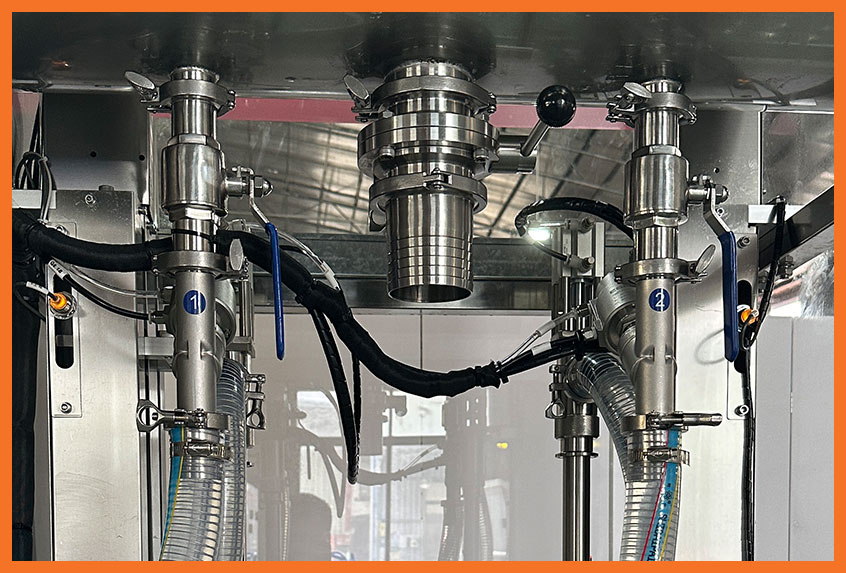
  • Dimple-Jacketed Piping: Circulate hot water or thermal oil through dual-wall manifolds and hoppers to hold product within precise temperature and viscosity limits.
  • Electric Heat Tracing with Insulation: Maintain steady fluid temperatures across long pipe runs between bulk storage and the packaging line to prevent product thickening during brief line stops.
  • Thermal Expansion Control: Include thermal relief valves in jacketed, isolated piping sections to prevent over-pressurization during heating cycles.
Large-bore filling pump

5. Step-by-Step Engineering Sizing Workflow and Math Formulas

Sizing a pump, product path and nozzle requires a defined duty and product measurements. These four steps distinguish preliminary calculations from the OEM checks and sample tests needed before final dimensions and drive limits are approved.

Step 1: Document Fluid Rheology, Specific Gravity, and Particulate Geometry

Before crunching mechanical numbers, we profile the exact physical behavior of the product under target factory floor temperatures:

  • Dynamic Viscosity (cP): Record temperature, representative shear-rate range, instrument/geometry, method and sample history. One cP value does not fully describe a shear-thinning or thixotropic product. Tetra Pak’s measuring guidance explains why process-representative conditions matter.
  • Density / Specific Gravity: Record density at process temperature and use it consistently for mass/volume and pressure/head conversions. Do not add bar directly to metres of liquid.
  • Particulate Dimensions: Measure the largest rigid particle diameter along its longest axis. Record particulate softness, shear sensitivity, and volume percentage in the slurry.

Step 2: Calculate Target Flow Rate per Nozzle Based on Cycle Time and Fill Volume

Define the actual timing sequence. In an indexed, non-overlapping example, effective fill time is total cycle time minus handling overhead. Continuous or overlapping machines need their own timing model, and cylinder refill must also fit the sequence.

  • Illustrative timing: Assume a 3.0 s cycle and 1.2 s non-overlapping handling overhead. Effective fill time is 3.0 − 1.2 = 1.8 s. These are chosen inputs, not recorded GDHP operating data.
  • Flow per nozzle: Q = V/t. For an illustrative 500 mL dose, Q = 500/1.8 = 277.8 mL/s = 16.7 L/min while filling. Average delivered volume over the complete 3.0 s cycle is 10 L/min per head. Size shared feed systems for simultaneous heads, buffering and refill timing, not merely the single-head average.

Step 3: Compute Total Dynamic Head (TDH) and Line Friction Loss

For a Newtonian, incompressible liquid in steady, fully developed laminar flow through a straight circular pipe, use the Hagen–Poiseuille relationship. Re = ρvD/μ < 2,000 is a laminar-flow screening check for the Newtonian example, not a substitute for a non-Newtonian model. For shear-dependent foods, see Tetra Pak’s rheology and pressure-drop discussion.

ΔP = 128μLQ/(πD4)
Use μ in Pa·s, L and D in m, and Q in m³/s to obtain ΔP in Pa. Conversions: 1 cP = 0.001 Pa·s; 1 L/min = 1/60,000 m³/s; 1 bar = 100,000 Pa.

To avoid high line resistance: Calculate friction loss for each straight tubing run, elbow, manifold junction, and valve port. Convert fitting friction into equivalent pipe lengths. Add the static vertical lift head (elevation rise from supply reservoir to nozzle tip). Add backpressure generated across the nozzle exit orifice.

Keep head and pressure consistent: Convert pressure using H = ΔP/(ρg), g ≈ 9.81 m/s², before adding lift in metres. Include actual valve, bend, nozzle and inlet losses and transient operation. The Section 4 table gives straight-pipe results only, not a pressure rating or final selection.

Step 4: Select Pump Displacement and Nozzle Bore with Engineering Safety Margins

With target flow rate and pressure loss (Delta P) established, size the final hardware:

  • Nozzle Bore Sizing: D = √(4Q/(πv)). Choosing an illustrative 1.5 m/s for a first calculation gives D ≈ 15.4 mm at the example flow. A 6 mm maximum particle dimension and the chosen 3:1 screening allowance instead give an 18 mm candidate, at about 1.09 m/s. Check actual nozzle and valve geometry, particle integrity and bottle opening; neither 1.5 m/s nor 3:1 is a universal acceptance limit.
  • Pump Displacement and Cycle: Use Section 2’s swept-volume calculation, then verify intake, discharge and handling timing. Percentage of maximum cycle speed is not percentage of piston stroke. Use the actual operating window, not a generic 60–75% maximum-speed rule.
  • Motor Torque and Drive Margin: Use the same supplier-approved duty and overload checks as Section 2. For piston drives, calculate F = ΔP × piston area, then include transmission geometry, friction and acceleration. For rotary shafts, use T = 9,550P/n. Do not apply a separate blanket 25% margin here.

Cycle-time sensitivity example, not a viscosity test: Increasing the illustrative 1.8 s effective fill time by 30–60% gives 2.34–2.88 s. With unchanged 1.2 s overhead, the total cycle becomes 3.54–4.08 s, up 18–36%. The theoretical single-head rate changes from 20.0 to 16.9–14.7 cycles/min. This shows why fill-time and total-cycle changes differ; it does not predict the behavior of a 50,000 cP paste.
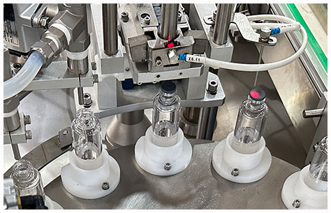
Precision small-bottle filling

6. Troubleshooting Common Viscosity and Particle Filling Bottlenecks

Running viscous pastes and chunk-filled suspensions at high speeds exposes every weak point in your fluid path. When lines choke, nozzles drip, or particulates get crushed, production stalls. As a filling machine manufacturer, we troubleshoot these issues daily on factory floors. Here is how we isolate and resolve the most common flow bottlenecks.

Fixing Pump Cavitation and Starved Suction Lines

Inadequate inlet replenishment can cause short fills. Cavitation specifically involves local pressure falling below vapor pressure; air entrainment or incomplete refill can produce similar symptoms without being the same mechanism. Check the inlet balance, temperature and timing before choosing a remedy.

  • Check suction-line diameter: Recalculate loss using actual flow and bore, then follow the pump’s inlet requirement. Increasing by one nominal size may help a particular layout but does not guarantee adequate feeding.
  • Shorten intake distance: Mount the pump directly below the supply hopper to minimize friction loss across the feed run.
  • Use an engineered feed arrangement: Assess a suitable hopper, auger or follower system with the OEM. A viscosity such as 50,000 cP does not authorize vessel pressurization. No generic 0.5–1.5 bar head-pressure setting is recommended: a pressurized feed vessel needs a rated design, pressure regulation, relief, interlocks and an approved procedure. Never pressurize an open or unrated hopper.
  • Ramp down suction stroke velocity: On servo-driven piston fillers, slow down the intake draw speed while keeping the discharge stroke fast. This gives heavy products time to fill the cylinder completely.

Eliminating Nozzle Dripping, Tailing, and Uneven Batch Fill Weights

Drips and stringing contaminate container seals, create burning on induction sealers, and waste costly product. Inconsistent shut-off mechanisms are almost always the root cause.

  • Tune the suck-back stroke: Program a micro-retraction stroke at the end of each piston cycle to break fluid surface tension at the nozzle orifice.
  • Switch to positive shut-off nozzles: For stringy or high-surface-tension products, replace open bore tubes with internally or externally seating positive shut-off nozzles. An internal shut-off pin cuts product cleanly right at the discharge tip.
  • Stabilize product temperature: Tetra Pak, Measuring techniques notes that a 3°C change can often cause a 10% viscosity change. This illustrates sensitivity, not a coefficient for every formulation; measure the actual direction and magnitude. Do not assume every 5°C cooling step doubles viscosity.
  • Inspect air entrapment: Air bubbles trapped in the pump cylinder or nozzle compress during the pressure stroke and expand after shut-off, causing post-fill dripping. Bleed all air before production runs.

Preventing Particulate Crushing, Settling, and Uneven Multi-Head Distribution

Pumping fruit chunks, salsa, or industrial suspensions requires delicate handling to maintain inclusion integrity and ensure equal solid-to-liquid ratios across all filling heads.

  • Review valve geometry and timing: A rotary product valve may improve passage but is not automatically shear-free. Check opening, closing action and OEM particle limits; compare particle integrity and solid-to-liquid ratio across heads in the trial.
  • Maintain active hopper suspension: Dense solids sink, while low-density solids float. Integrate low-shear, horizontal ribbon or anchor agitators to keep particles uniformly suspended without macerating the product.
  • Balance multi-head delivery manifolds: Split manifolds symmetrically with equal-length sweep bends. Avoid straight T-junctions, which cause solids to shoot past inner heads and load disproportionately into the outer nozzles.
  • Recheck every restriction: The 3:1 assumption is an initial screening calculation. A tighter manufacturer limit, or bridging or damage found in testing, governs the design. Softness does not automatically justify a smaller passage.

Managing CIP and SIP for Sticky, Particulate-Laden Lines

Sticky formulations, starches, and heavy fats resist standard clean-in-place cycles, creating contamination hazards and valve sticking.

  • CIP pipeline velocity: Tetra Pak’s cleaning guidance and Alfa Laval handbook, printed p. 285 describe 1.5–3.0 m/s for cleaning-fluid flow in pipelines. Apply this to the actual cleaning circuit, soils, time, temperature, detergent concentration and equipment ratings. It is not a viscous-product filling velocity, and velocity alone does not validate cleaning.
  • Dead legs and blind tees: Apply Section 4’s circuit-specific hygienic specification. Check drainability, branches, valve actuation and cleaning coverage; L/D alone does not demonstrate a clean system.
  • Program forward and reverse pulsing: Cycle automated piston strokes and pulse diving nozzles during the wash cycle to expose internal dynamic seals, O-rings, and valve seats to cleaning detergents.
  • Choose pre-rinse temperature for the residue: Tetra Pak’s dairy guidance says warm water helps flush milk fat but should not exceed 55°C to avoid protein coagulation. Alfa Laval’s generic example starts with an ambient-temperature rinse. These are different contexts, not one recipe. Select and validate the sequence for the actual formulation. SIP, if required, needs separate sterilization validation.

Have questions? Reach out to us, and we will provide you with a perfect solution.

FAQ

There is no universal maximum for a standard piston nozzle. The article’s 3:1 clearance ratio is an assumed screening example, not a guarantee. A particle with a 10 mm maximum measured dimension gives a 30 mm initial bore candidate; valves and other restrictions still need checking. Do not automatically reduce the ratio for soft inclusions. UNIFILLER lists up to 38 mm cubes for the Pro 2000i FS with specified passages, subject to product confirmation. Cube side length, spherical diameter and an irregular particle’s longest dimension are different conventions.

Some piston or progressing-cavity platforms cover both after suitable tooling and setting changes, but compatibility is not automatic. Check model-specific viscosity, inlet-feed, seal, valve and temperature limits. Thin liquids may need different shut-off and diving settings; pastes may need larger clear passages and slower intake. Test both products with the actual container, dose and required output.

Shear can change structure, viscosity or aeration, depending on formulation, shear rate and exposure time. Tetra Pak’s rheology guidance distinguishes shear thinning from time-dependent behavior; temporary thinning is not automatically permanent damage. Compare incoming and filled product using agreed texture, inclusion-integrity and stability checks, rather than assuming every gear pump damages emulsions or every low-shear pump preserves them.

There is no universal acceptable pressure drop of 20–30 psi (approximately 1.4–2.1 bar). The pressure budget depends on the pump, tubing, seals, valves, nozzle and temperature, with adequate inlet conditions and pressure protection. Section 4’s Newtonian calculation gives 5.79 bar for 2 m of 25 mm actual-ID pipe, 1.09 bar at 38 mm, and 0.335 bar at 51 mm, excluding fittings and lift. Calculate the complete duty and check each component’s rating; one pressure band is not safe for all lines.

Build Your Custom Solution

Your information is secure - we respect your privacy and will only use these details to contact you.

Build Your Custom Solution