Hot-Fill Gel Filling Line Case: Cooling and Format-Specific Capping
October 20, 2026
See how a hot-fill gel line uses a 9 m cooling tunnel and separate cap, film and induction-seal routes for different packs.
John
Hello, I am a senior engineer and founder at GDHP. With 23 years of technical expertise in the filling and packaging industry, we provide more than just equipment—we are dedicated to delivering high-stability, high-efficiency, and fully customized turnkey solutions for your business.
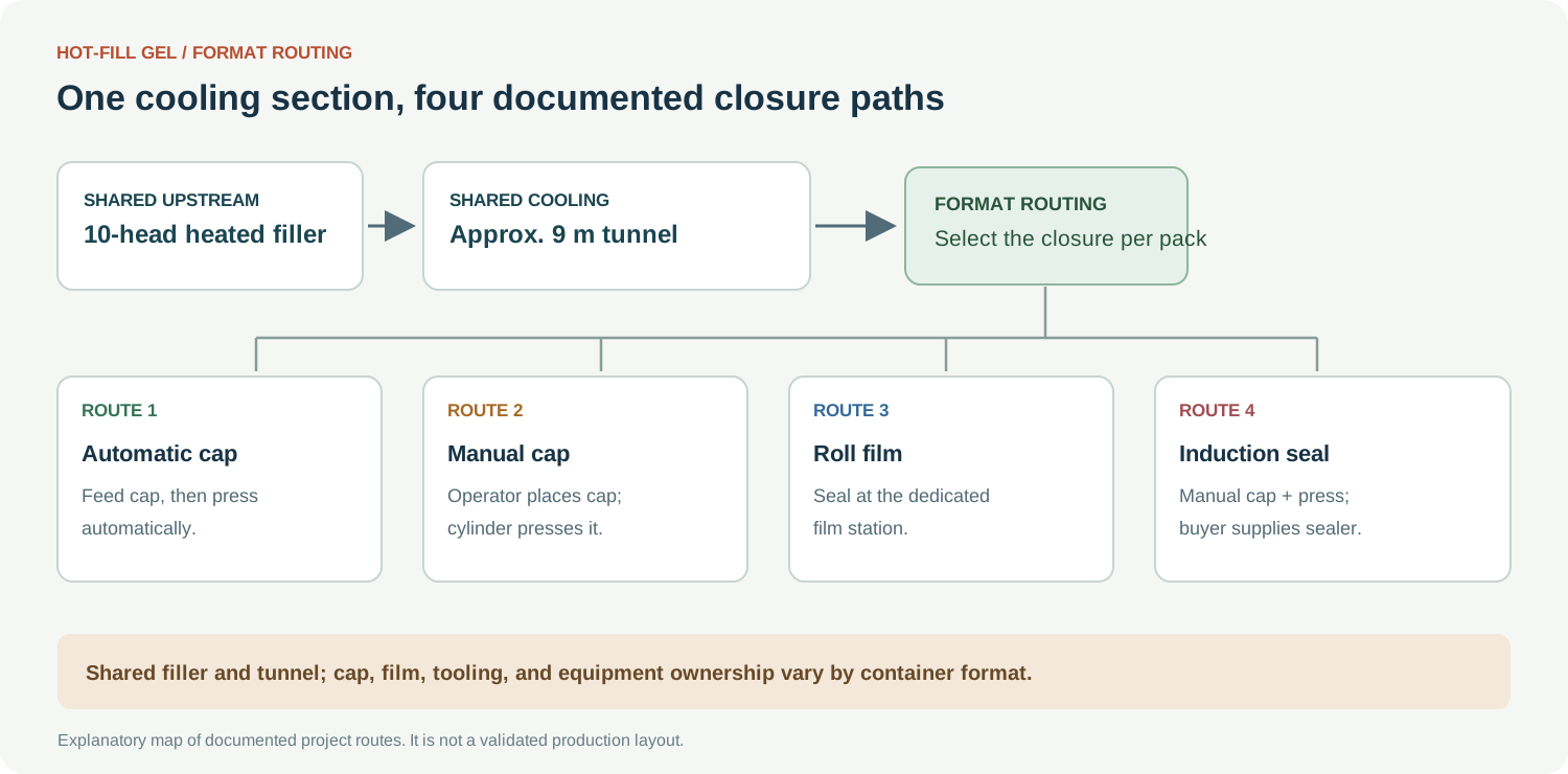
When I review a hot-fill gel line, I start with the closure route rather than the filler name. In this project, several container formats share the heated filling and cooling section, then branch into different capping or sealing operations. That branch is the engineering feature that determines the change parts, operator work and downstream interfaces.
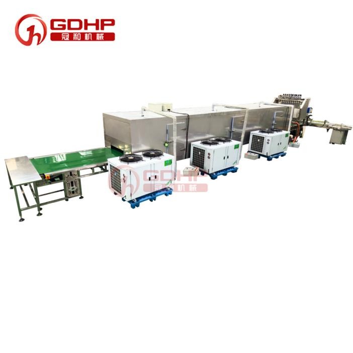
The line is arranged around a 180 g air-freshener gel fill, a ten-head heated filler and an approximately 9 m cooling tunnel with three 10 hp cooling units. I treat the stated 4,000 bottles per hour as a design reference for that fill condition, then set the final recipe with the actual gel and container.
Pack route
What happens after cooling
What I set up first
Automatic cap
Bowl-fed cap is placed and pressed
Cap orientation, bottle support and press height
Manual-cap format
Operator places the cap and a cylinder presses it
Operator position, bottle pitch and cap alignment
Roll film
Roll film is sealed at a dedicated station
Film width, mouth geometry, heat and dwell
Buyer-supplied induction seal
Cap is placed and pressed before the buyer’s sealer
Conveyor hand-off, sealer position and ownership boundary
Equipment view of the cooling section used to explain the residence-time problem.Process illustration: the upstream thermal path is shared, while the closure equipment changes with the container format.
Why the matrix matters
Some formats use dedicated fixtures and some do not. I therefore set the conveyor guides from the smallest stable bottle reference first, then check the larger format for clearance at the tunnel turns and at the first closure station. The outer size of the largest bottle alone is not enough to define the guide arrangement.
The shared section includes a mixing tank, heated product supply, a ten-head filler and touchscreen temperature control. Product-contact parts are stainless steel 316 and the machine frame is stainless steel 304. The tank, pump, hopper level and nozzle need to be reviewed as one thermal path; heating only the filler can leave a cold spot upstream.
The thermal hand-off starts before the nozzle
For the heated product, I set the mixing temperature, replenishment level and filling temperature together. The gel’s setting behavior, foaming and permitted hold time decide whether the pump and pipe need additional heat retention. The operator should be able to see a low-level condition before the filling head draws air or the line moves into a different closure route.
Thermal point
Practical observation
Why it matters downstream
Mixing tank
Temperature, agitation and working level
A stable feed gives the filler a repeatable product condition
Hopper
Level recovery after a fill cycle
Low level can cause air, drips or a change in fill appearance
Nozzle
Rim wetting, stringing and restart behavior
A clean mouth is needed for cap or film sealing
Tunnel exit
Gel surface and bottle spacing
The next station must receive a stable, correctly located bottle
Cooling is a residence-time problem
The tunnel is approximately 9 m long, with conveyor speed adjustable from 3 to 15 m/min and three 10 hp cooling units. Those values give me a useful starting window. During the product run, I look at the gel at tunnel entry and exit, bottle spacing through the turns and the mouth condition when the container reaches its cap or seal station.
A short stop deserves its own check. Gel left in a nozzle, pipe or bottle can change state while the conveyor is stationary, so the first container after a restart is more informative than a smooth middle run.
Keep ownership boundaries visible
The induction sealer in this layout is supplied by the buyer. I define its conveyor height, signal exchange, bottle orientation and emergency-stop connection before calling the upstream line ready. The filler and tunnel can run correctly while the downstream sealer still lacks a usable hand-off.
For each format, I keep four items in the setup sheet: the cap or film supplied, the station that performs the closure, the physical change parts and the restart action after a stop. This makes a format change a real operating procedure instead of a new value typed into the touchscreen.
A better trial sequence for this case
Heat and mix the actual gel, then run the ten-head filler with the selected bottle support.
Check tunnel entry and exit condition at a stable conveyor speed.
Run automatic-cap and manual-cap formats separately, including a short stop and restart.
Tune the roll-film route with its actual film width and bottle mouth.
Connect the buyer’s induction sealer after the conveyor and control interface are defined.
The project is a good example of why hot filling, cooling and closure should be designed as one format matrix. The 9 m tunnel and ten-head filler are shared anchors; cap, film, fixtures and the downstream owner change with the pack.