
Explosion-Proof Disinfectant Filling: A 30–100 mL Line Designed for 100 BPM

Hello, I am a Senior Engineer and Founder at GDHP. With 23 years of technical expertise in the filling and packaging industry, we provide more than just equipment—we are dedicated to delivering high-stability, high-efficiency, and fully customized turnkey solutions for your business.
Table of Contents
An alcohol disinfectant can look easy to fill because it is thin and free-flowing. The real difficulty appears around the filler: volatile vapor, static charge, fast-flowing liquid, lightweight bottles and several possible ignition sources must be controlled as one production system.
Increasing speed makes those interactions more demanding. A faster infeed can destabilize small bottles, an abrupt fill can splash product onto the neck, and an ordinary motor, sensor or electrical cabinet may be unsuitable for the classified area. Adding a component labeled “explosion-proof” does not by itself make the complete line suitable.
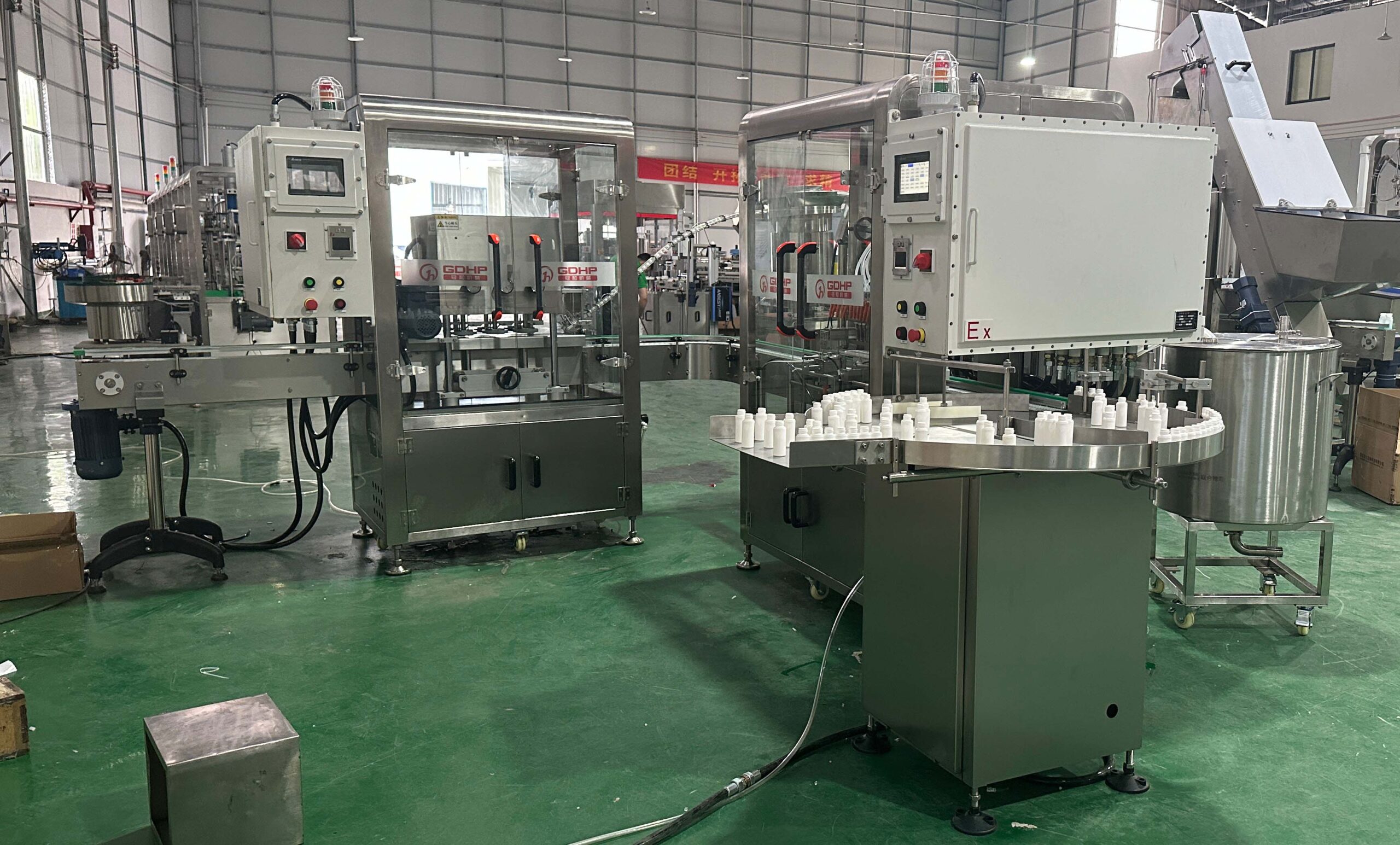
This case explains how one explosion-proof disinfectant filling line was specified for 30, 60, 80 and 100 mL bottles, with a design target of 100 bottles per minute. The proposed sequence combined bottle feeding, 12-head peristaltic filling, automatic capping, induction sealing and missing-foil rejection.
Why Alcohol Disinfectant Changes the Filling Line Design
The liquid is only one part of the engineering problem. Its vapor, the packaging materials and the surrounding production area determine what equipment can be used and how the stations should be arranged. An alcohol disinfectant filling machine therefore has to control the product path, container transfer and ignition sources together.
Flammable vapor makes ignition control a line-level decision
Alcohol vapor can be released at the supply tank, tubing connections, filling nozzles and spills. For reference, the U.S. National Oceanic and Atmospheric Administration lists a 55°F (about 13°C) flash point for pure ethanol and describes its vapor as heavier than air. The finished disinfectant may have a different composition and flash point, so the product safety data sheet must govern the project rather than the pure-solvent value.
NOAA’s CAMEO Chemicals ethanol data also shows why ventilation and low-level vapor accumulation deserve attention. The figure is a hazard reference, not a substitute for testing or classifying the customer’s actual formulation.
Thin liquid can splash, drip and contaminate the sealing area
Low viscosity helps the product move quickly through tubing, but it also makes the end of the fill harder to keep clean. Excess speed or a poor nozzle shut-off can leave drops on the bottle shoulder or thread. That residue can interfere with cap handling and foil sealing, so the filler must control both dose and cut-off.
Small bottles need controlled transfer
The 30 and 60 mL bottles in this project were more sensitive to conveyor gaps, guide pressure and sudden acceleration than a wide, heavy container. A line can meet the filler cycle rate and still fail its output target if bottles tip at the infeed or queue before capping. Bottle stability therefore had to be checked across the complete size range.
The Project Brief: Four Bottle Sizes and a 100 BPM Design Target
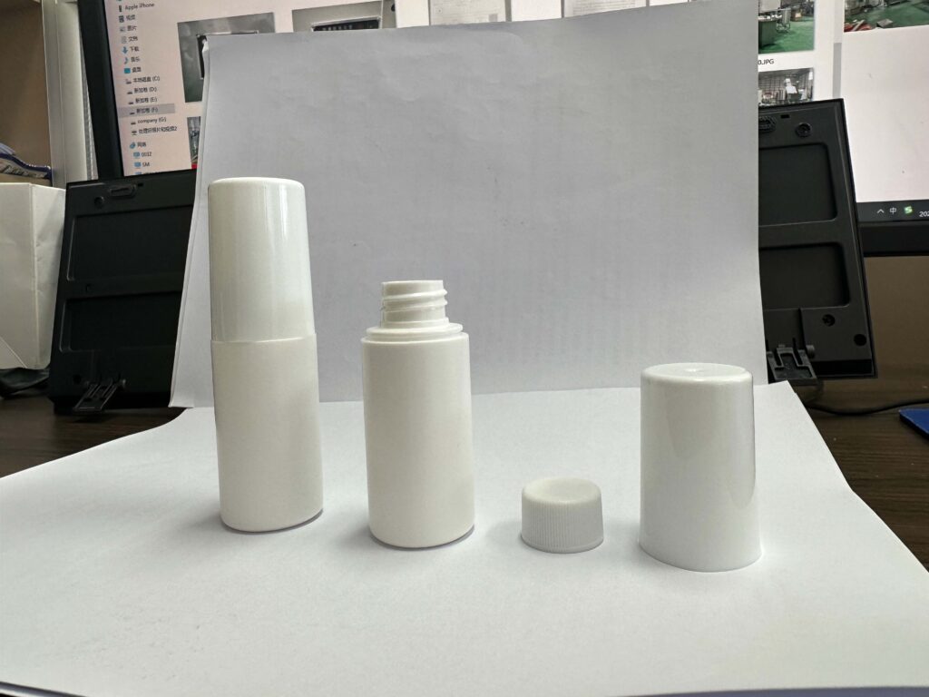
The existing process was described as a 60-bottle-per-minute arrangement. The new specification targeted 100 bottles per minute while handling four round-bottle formats: 30, 60, 80 and 100 mL.
The project documentation called for explosion-protected equipment, anti-static measures, stainless-steel construction and programmable logic controller control. The filling system used peristaltic metering with a 50 L product tank and level control. Downstream, the line included automatic cap sorting and cap feeding, capping, induction sealing and inspection for a missing foil liner.
| Item | Project requirement or proposed configuration |
|---|---|
| Product | Alcohol-based disinfectant; project documentation identifies an isopropyl-alcohol formulation |
| Bottle sizes | 30, 60, 80 and 100 mL |
| Output basis | 100 bottles/minute design target; final acceptance must define the bottle and fill size used for the test |
| Filling station | 12-head peristaltic pump filling system |
| Product supply | 50 L tank with level control; supply interface to be agreed with the customer’s feed system |
| Closure | Automatic cap sorting, cap feeding and explosion-protected capping configuration |
| Seal inspection | Induction foil sealing followed by missing-foil detection and rejection |
For buyers comparing an explosion-proof disinfectant filling machine, these figures describe the project brief and proposed machine architecture. They should not be read as proof that every disinfectant, bottle or facility will achieve the same output.
The Explosion-Proof Disinfectant Filling Line Sequence
The machine choice followed the order in which containers and product moved through the line. Each station had to suit the bottle, the speed target and the hazardous-area plan.
Proposed case process
- 01 · INFEEDRotary bottle feeding and controlled discharge
- 02 · FILLING12-head peristaltic metering from a level-controlled tank
- 03 · CAP FEEDAutomatic cap sorting, orientation and placement
- 04 · CAPPINGContinuous bottle support and controlled tightening
- 05 · FOIL SEALInduction sealing at the assessed downstream location
- 06 · INSPECTIONMissing-foil detection and reject handling
Rotary bottle feeding
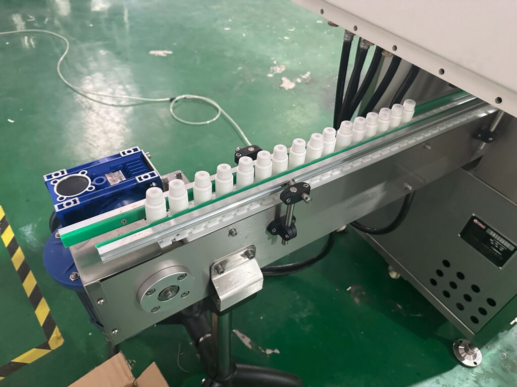
The infeed accumulated upright bottles and released them into a single lane. The project description specified an explosion-protected drive for this station. Adjustable guides and a controlled discharge were needed because the same line had to handle four small bottle sizes without allowing light containers to collide or tip.
Capping and sealing
Automatic cap sorting reduced dependence on manual placement at the target rate. The capping station had to support the bottle while applying the required closure condition. Induction sealing and missing-foil inspection were included downstream, but their final position and protection scope require separate review because the induction system is an electrical energy source.
Why the Case Used 12-Head Peristaltic Filling
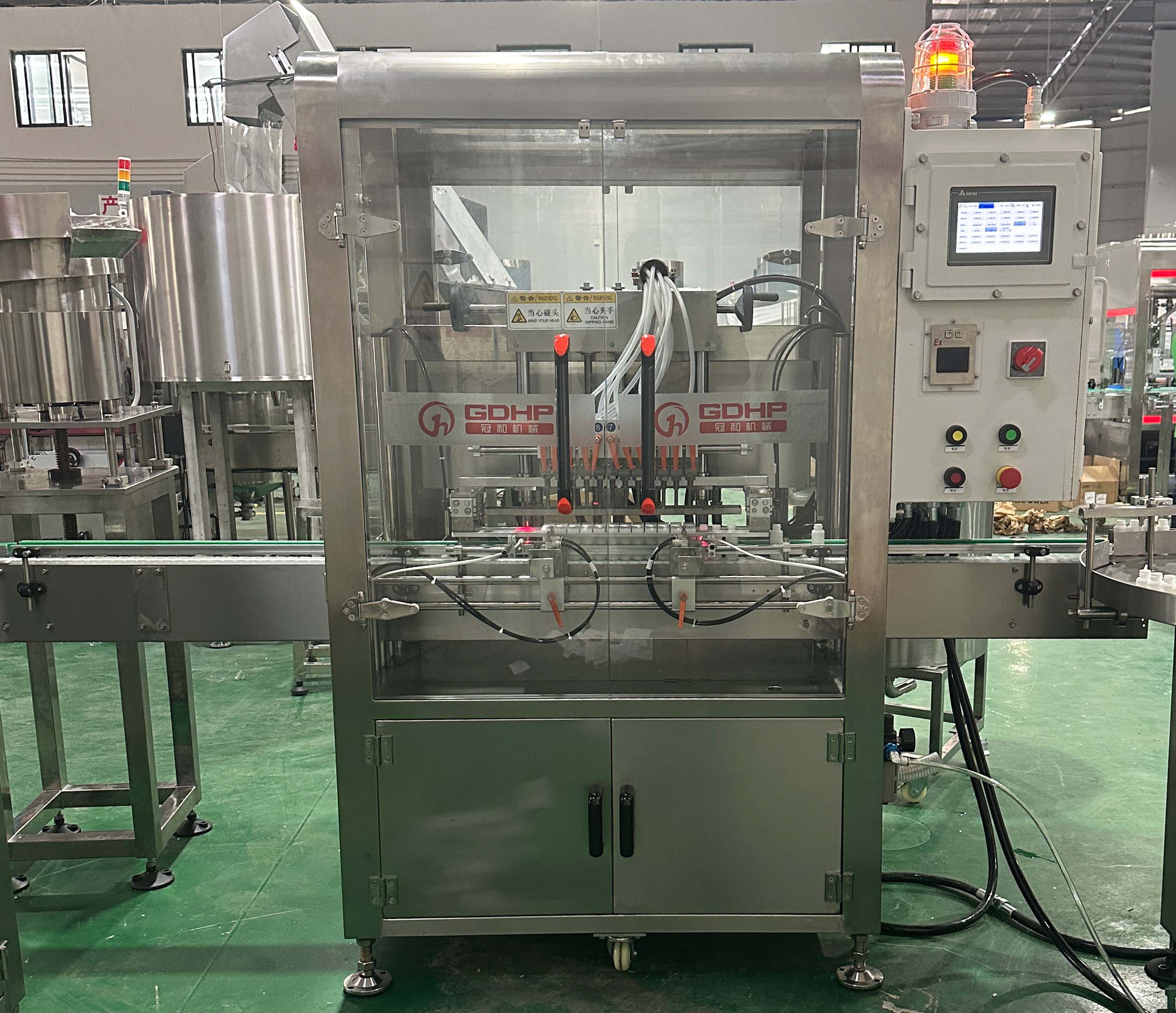
A peristaltic pump meters liquid by compressing flexible tubing. The product path is concentrated in the tubing, connectors and nozzle instead of passing through the pump mechanism. For this project, that layout supported small-dose filling and a defined, replaceable contact path.
Twelve heads supported the line balance
At 100 bottles per minute, the filling station could not be selected in isolation. Twelve parallel heads spread the dosing work across multiple containers while leaving time for indexing, nozzle movement and transfer. The exact cycle still depends on the largest dose, pump speed, tubing size, acceleration, priming condition and the time available for a clean cut-off.
Tubing simplifies the wetted path, but it must be validated
Peristaltic filling can make product change and cleaning easier because the liquid-contact path is accessible. It does not remove the need for chemical compatibility testing. Tubing material, wall thickness, service life, compression setting and alcohol exposure can all affect calibration and replacement intervals.
The GDHP chemical filling system guide explains how the material, container, output, wetted path and site conditions should be specified together.
The pump is not the explosion-protection strategy
A peristaltic pump is a dosing method. Its motor, drive, sensors, wiring and control arrangement still have to match the classified location. The same applies to the bottle feeder, conveyor, capping station, valves and inspection equipment. The engineering question is whether the complete installed system is suitable for the identified vapor hazard.
What “Explosion-Proof” Must Cover Beyond the Filler
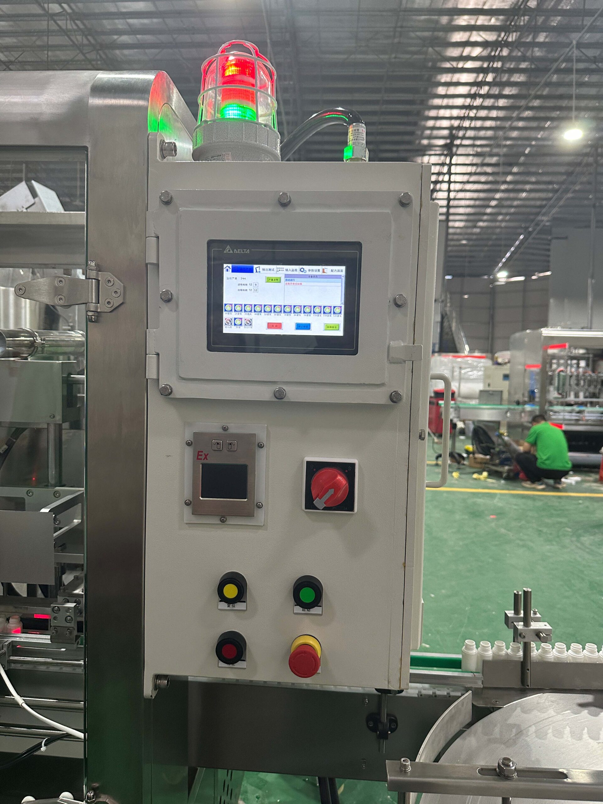
The term should describe a documented protection scope, not a stainless-steel frame or a guarded enclosure. Start with the formulation safety data sheet and the facility’s hazardous-area classification, then specify the required protection method for every relevant device and interface.
Classify the area before selecting components
For U.S. facilities, OSHA 29 CFR 1910.307 requires hazardous areas to be documented and electrical equipment to be intrinsically safe, approved for the classified location or otherwise demonstrated safe for that location. It also says equipment selection must account for the ignitable properties of the specific gas or vapor present.
Other countries use different legal and certification frameworks. The site owner and qualified safety professionals must identify the applicable classification, certificates and installation rules before the machine specification is finalized.
Control ignition sources and static through the process
OSHA 29 CFR 1910.106 lists static, electrical and mechanical sparks among possible ignition sources for flammable vapor. For defined categories of low-flashpoint liquids, the U.S. rule also requires electrical interconnection between the nozzle and container during dispensing. The practical design must account for container material, grounding and bonding method, filling geometry and local requirements.
In this case, the specification referenced explosion-protected motors and cabinets plus anti-static measures. Those are parts of the solution. Ventilation, vapor release points, earthing continuity, cable entries, sensor selection, emergency stops and downstream equipment still need to be included in the same risk review.
A safe scope is explicit. The project documents should state which stations are inside each classified area, the required equipment markings, who supplies ventilation and grounding interfaces, and which checks must pass before operation.
GDHP’s explosion-proof filling line overview can help define the equipment modules. The final selection still depends on the formulation and the customer’s site assessment.
Factory Acceptance Checks for This Disinfectant Case
A factory acceptance test should prove the agreed machine functions under recorded conditions. It should use representative bottles, caps and liners, together with the intended product or an agreed test liquid whose behavior is understood.
- Bottle handling: run all four formats through accumulation, guides and transfers. Record tipping, scuffing, jams and recovery after a short stop.
- Fill quantity: define the target, tolerance, sampling method and measurement basis. Check each filling head at startup and after a sustained run.
- Drip and neck cleanliness: inspect the bottle shoulder, thread and sealing surface after normal running, pauses and restart.
- Output: measure accepted bottles through the complete agreed sequence at the specified test format. Do not report filler indexing speed as finished-line output.
- Closure quality: verify cap presence, placement and the agreed torque or closure test without deforming the small bottles.
- Foil inspection: challenge the missing-foil detector with known defect samples and confirm the reject response.
- Safety functions: test alarms, emergency stops, interlocks and loss-of-utility responses within the agreed protection scope.
- Format change: document change parts, recipe values, guide settings and the checks required before the first acceptable bottle.
Site acceptance must then confirm the installed utilities, ventilation, grounding, equipment markings and interfaces that cannot be proven on the supplier’s factory floor.
When This Explosion-Proof Filling Case Is a Useful Reference
This configuration is relevant when the product is an alcohol-based, low-viscosity disinfectant in small bottles and the project needs coordinated bottle feeding, filling, capping, foil sealing and inspection. It is especially useful as a starting point when several bottle sizes must share one line.
It should not be copied without review. A water-based disinfectant may not need the same hazardous-area scope. A corrosive formulation may require different tubing, seals or metals. A foaming product may need a different nozzle movement or filling profile. A site with a different classification may also require a different electrical design and documentation package.
The practical next step is to compare the case assumptions with the actual safety data sheet, container samples, closure, fill quantity, line speed and facility classification. Any mismatch should become an engineering requirement before a model is selected.
Questions About Explosion-Proof Disinfectant Filling
Is a peristaltic filling machine automatically explosion-proof?
No. Peristaltic describes the metering principle. Motors, drives, sensors, wiring, cabinets and all other equipment in the classified area still need a suitable protection method and approval for the location.
Can the same line fill ethanol and isopropyl-alcohol disinfectants?
Possibly, but compatibility and hazard review must use each formulation’s safety data sheet. Concentration, additives, flash point, vapor behavior and tubing compatibility can change the required settings and protection scope.
Does the 100 BPM target apply to all four bottle sizes?
The case records a 100 BPM design target and a 30–100 mL range. The acceptance test should name the bottle, dose and product condition used for the target. Larger fills and less stable bottles may change the sustainable output.
What should a buyer provide before line design begins?
Provide the safety data sheet, formulation and concentration, flash point, fill quantities, bottle and cap samples, foil-liner details, output target, hazardous-area drawing, local standards, utilities and intended line layout. Include the required test method for fill quantity, closure and reject functions.
Define Your Disinfectant Filling Application
Share your disinfectant safety data sheet, bottle and closure samples, fill range, required output and hazardous-area classification. GDHP can use those inputs to define the filling method, contact materials, explosion-protection scope, closure sequence and acceptance test plan.
Discuss an explosion-proof disinfectant filling line with GDHP.